Method of integrally molding connector, and object connector

a technology of connectors and connectors, applied in the direction of coupling device connections, manufacturing tools, securing/insulating coupling contact members, etc., can solve the problems of oil or the like running along the electric wire and spreading, and achieve the effects of enhancing the performance of molding, reducing the influence of bad influences, and changing the shap

Active Publication Date: 2012-02-16
YAZAKI CORP
View PDF9 Cites 25 Cited by
  • Summary
  • Abstract
  • Description
  • Claims
  • Application Information

AI Technical Summary

Benefits of technology

[0015]In the method of integrally molding a connector according to the invention, the elastic resin is bonded to the cover part, and the elastic resin is bonded to the resin and press-fitted to the terminal. Therefore, the elastic resin and the resin do not adhere to metal molds which are used in the first and second steps, and mold releasing performance can be enhanced. In this manner, it is possible to restrain bad influences such as deterioration of productivity, change in shape, and mass production can be achieved.
[0016]Moreover, in the second step, the resin is injection molded around the elastic resin so as to compress the elastic resin, and the elastic resin is press-fitted to the terminal thereby to seal a gap between the elastic resin and the terminal. As the results, there is no necessity of using other members for waterproofing the connector, and the number of components and assembling steps can be reduced.
[0017]Accordingly, it is possible to reduce the number of the components, and to enhance productivity.
[0018]Moreover, in the method of integrally molding a connector according to the invention, in the second step, the resin is injection molded around the region positioned adjacent to the connection part, out of the elastic resin which has been injection molded around the connection part, and the region positioned adjacent to the cover part, out of the elastic resin, is exposed. Therefore, a drawing part of the electric wire can be made flexible, while maintaining rigidity of the drawing part of the electric wire, and freeness in arranging the connector can be enhanced.

Problems solved by technology

In this connector, although the counterpart member side need not be sealed depending on type of oil-proofing or so, in some cases, there is such anxiety that oil or the like may run along the electric wire and spread, unless the connector side is sealed.

Method used


Image

  • Method of integrally molding connector, and object connector
  • Method of integrally molding connector, and object connector
  • Method of integrally molding connector, and object connector

Examples


Embodiment Construction

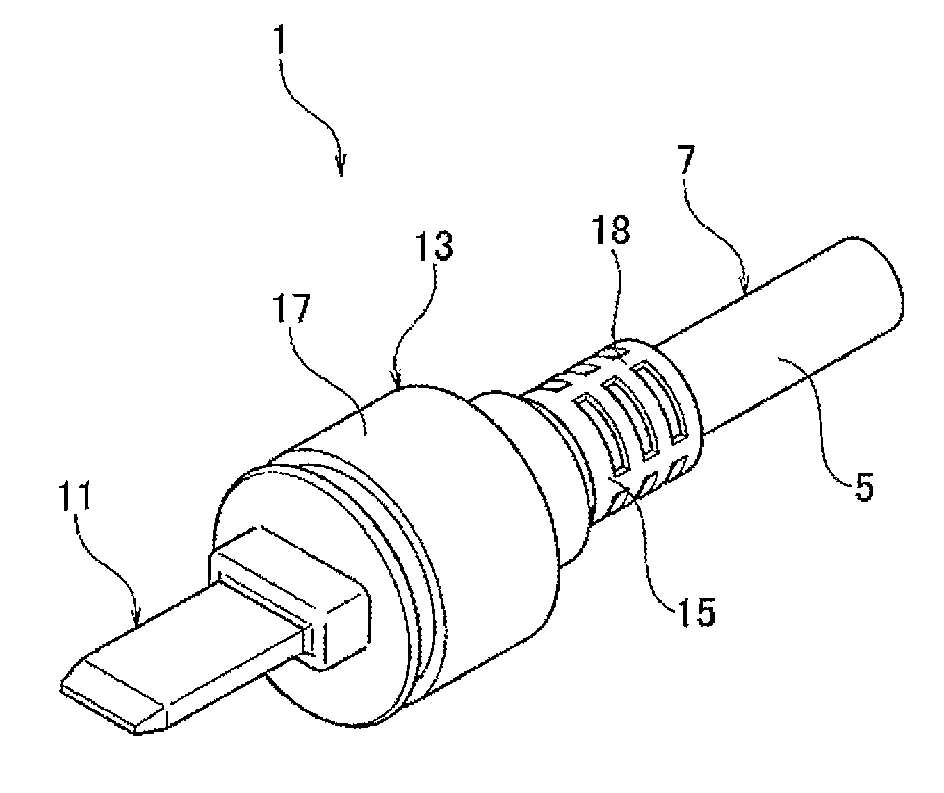
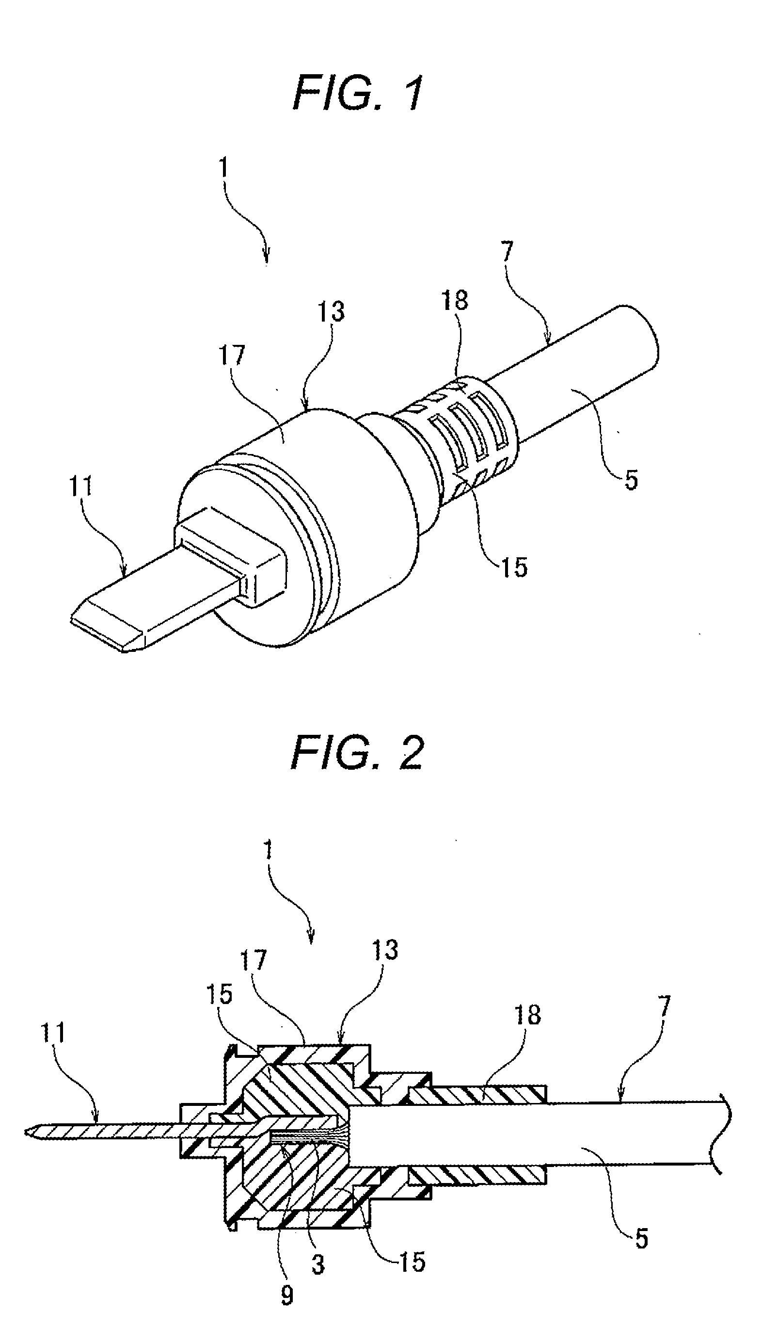
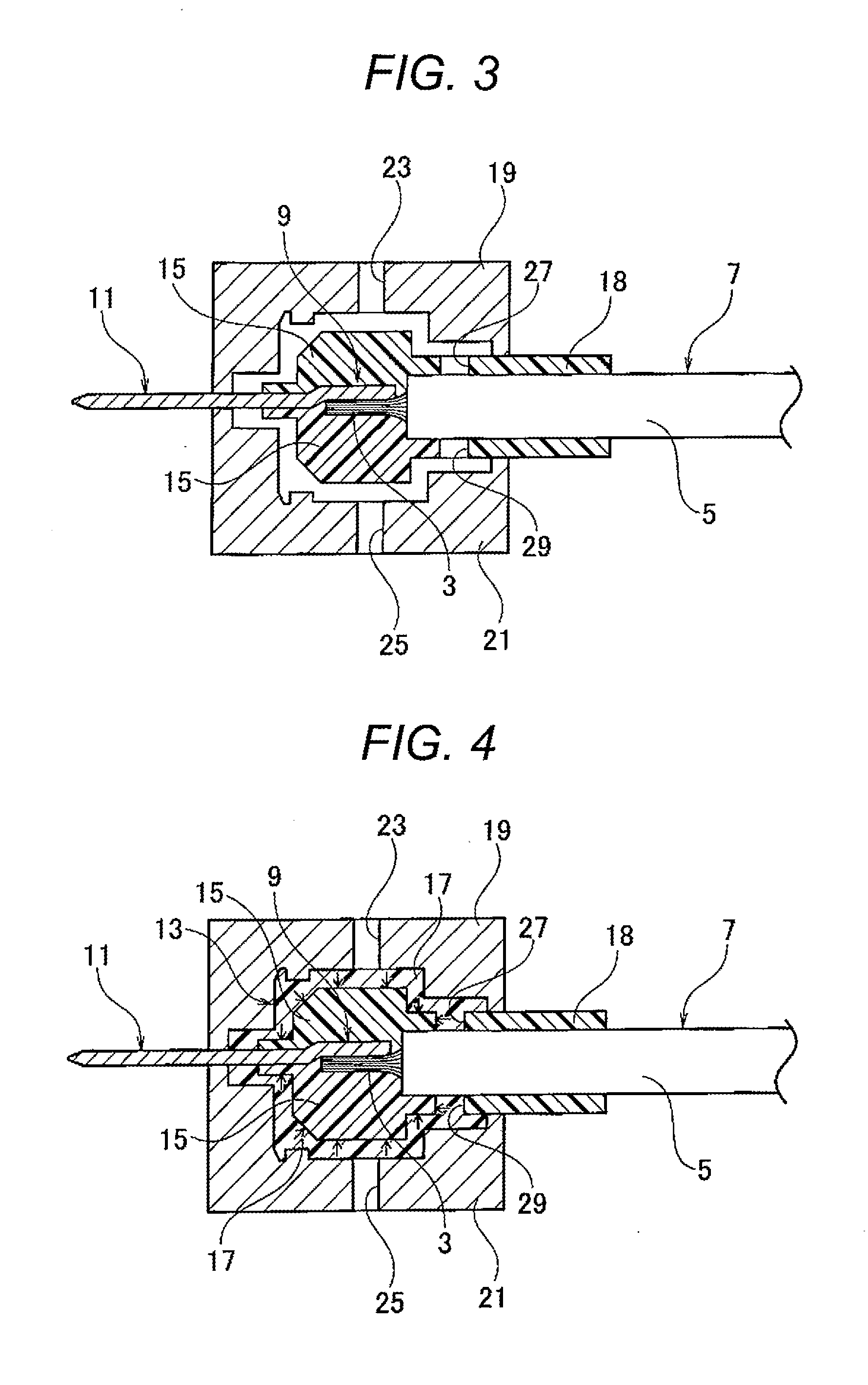
[0023]Referring to FIGS. 1 to 4, the connector in the embodiment according to the invention and the method of integrally molding the connector will be described.

[0024]A connector 1 in this embodiment includes an electric wire 7 of which a core part 3 is covered with a cover part 5, a terminal 11 having a connection part 9 which is connected to the core part 3 of the electric wire 7, and a covering member 13 which is provided around the connection part 9. Moreover, the covering member 13 includes elastic resin 15 which is provided around the connection part 9 and an end part of the cover part 5 positioned adjacent to the connection part 9, to be bonded to the cover part 5, and at the same time, press-fitted to the terminal 11, and resin 17 which is provided around the elastic resin 15 so as to compress the elastic resin 15, and bonded to the elastic resin 15.

[0025]This method of integrally molding the connector 1 includes a first step of injection molding the elastic resin 15 around ...


PUM


Abstract

There is provided a method of integrally molding a connector in which the number of components can be reduced, and productivity can be enhanced.The method of integrally molding a connector according to the invention includes a first step of injection molding elastic resin 15 around a connection part 9 and an end part of a cover part 5 of an electric wire which is positioned adjacent to the connection part 9 thereby to bond the cover part 5 and the elastic resin 15 to each other, and a second step of injection molding resin 17 around the elastic resin 15 so as to compress the elastic resin 15 thereby to press-fit the elastic resin 15 to a terminal 11, and at the same time, to bond the elastic resin 15 and the resin 17 to each other.

Description

TECHNICAL FIELD[0001]The present invention relates to a method of integrally molding a connector having waterproofing performance, and the object connector.BACKGROUND ART[0002]As the connector having waterproofing performance, there has been conventionally known such a connector that an electric wire and a housing are integrally molded out of thermoplastic resin, and a joint part between the respective members is sealed with thermoplastic resin (Reference should be made to Patent Document 1, for example).[0003]In the connector as described above, the waterproofing performance of the connector side depends on a shape of a counterpart member to be connected to the connector. In this connector, although the counterpart member side need not be sealed depending on type of oil-proofing or so, in some cases, there is such anxiety that oil or the like may run along the electric wire and spread, unless the connector side is sealed. In case where a sealing mechanism is required, it would be m...

Claims


Application Information

Patent Timeline
Patent Type & Authority Applications(United States)
IPC IPC(8): H01R13/405H01R13/52
CPCH01R43/24H01R13/504
Inventor YOSHIOKA, NOBUAKIMORITA, IKUO
Owner YAZAKI CORP
Why Eureka
Try Eureka