
Electrolytically driven drug pump devices

Inactive Publication Date: 2012-02-16
MINIPUMPS
View PDF4 Cites 40 Cited by
  • Summary
  • Abstract
  • Description
  • Claims
  • Application Information

AI Technical Summary

Benefits of technology

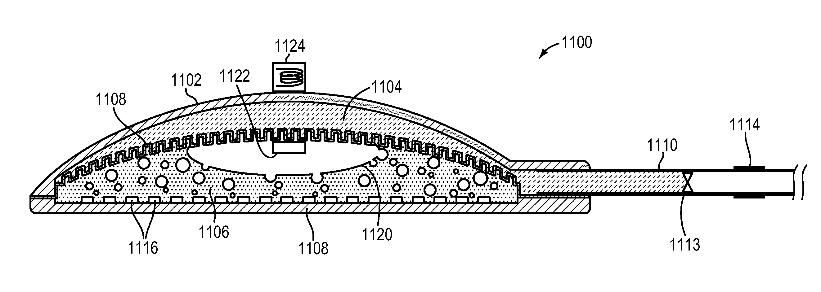
[0010]The vial may be formed from a conventional drug vial, and may be made of glass and / or a polymer. The electrolysis pump may be attached to the vial by a clamp-fit mechanism and sealed by a rubber O-ring. The electrolysis pump may have a back-end made of polymer, ceramics, anodized metal, or glass, with feed-throughs for connection to the external electrical circuit and associated power supply without loss of electrolyte fluid and without electrical shorting of the electronic circuit or battery. In some embodiments, the electrical circuit and associated power supply are sized based on a diameter of the electrolysis pump so as to fit as a cap thereon. In other embodiments, they are located adjacent the vial and are wire-connected to the electrolysis pump. The device may include a controller for facilitating device operation by an electronic handheld device via a wireless connection, or a mechanical selector for setting the drug dose to be delivered from the drug reservoir.

Problems solved by technology

For example, many chronic conditions, including multiple sclerosis, diabetes, osteoporosis, and Alzheimer's disease, are incurable and difficult to treat with currently available therapies: oral medications have systemic side effects; injections may require a medical visit, can be painful, and risk infection; and sustained-release implants must typically be removed after their supply is exhausted, and offer limited ability to change the dose in response to the clinical picture.
Such frequent injections can result in discomfort, pain, and inconvenience to the patient.
Self-administration further poses the risk of non-compliance or errors in dosage events.
As a result, the electrodes may gradually lose contact with the electrolyte, which affects the rate of electrolysis and, eventually, causes the electrolysis process to cease entirely.
Not only does this negatively affect the drug-delivery capacity of a pump device with a given electrolyte volume, but it also undermines the reliability of drug delivery because the effect tends to depend on the orientation of the device, and is, therefore, highly unpredictable (in particular, in patient-worn devices).

Method used


Image

  • Electrolytically driven drug pump devices
  • Electrolytically driven drug pump devices
  • Electrolytically driven drug pump devices

Examples


Embodiment Construction

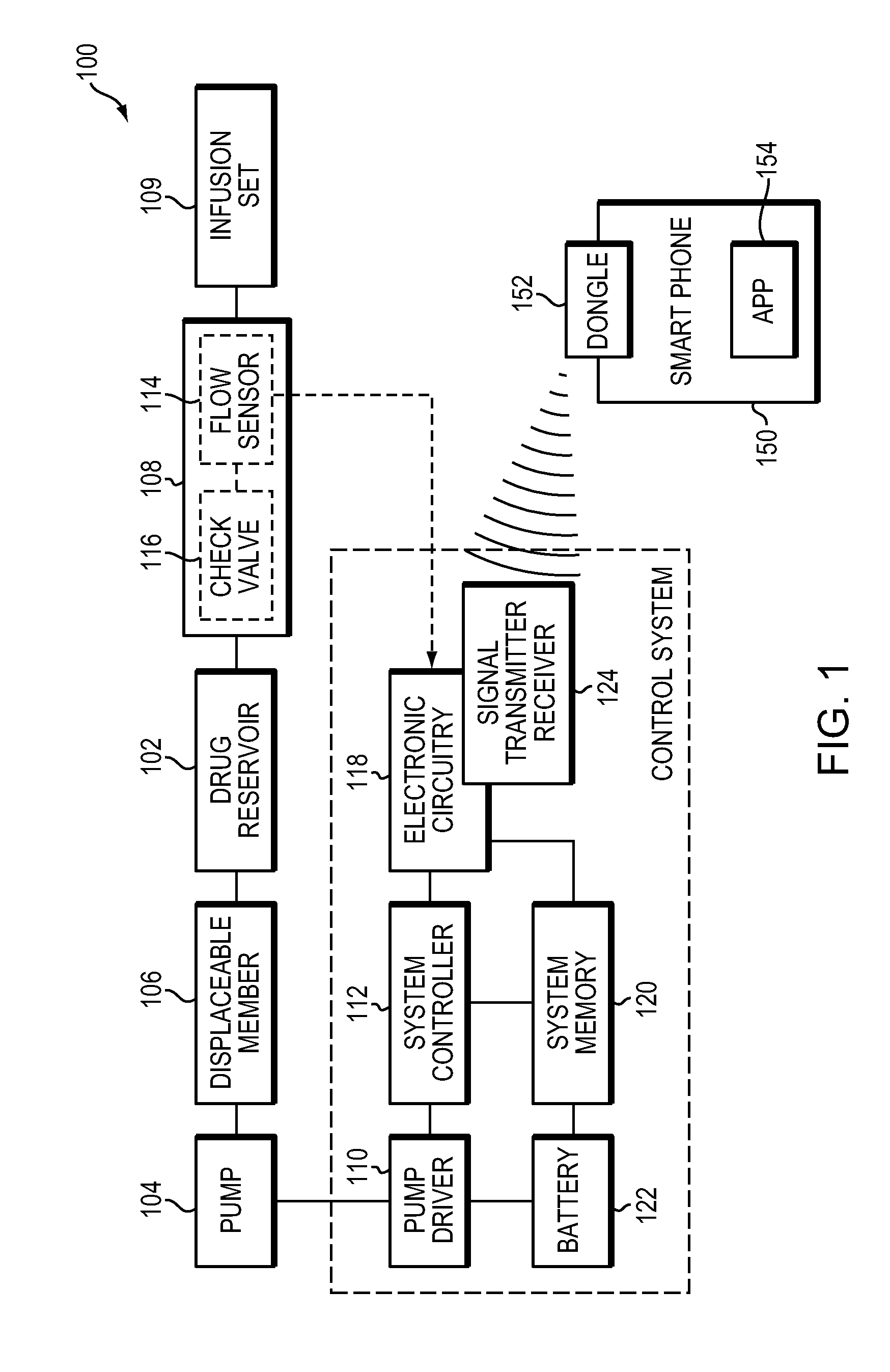
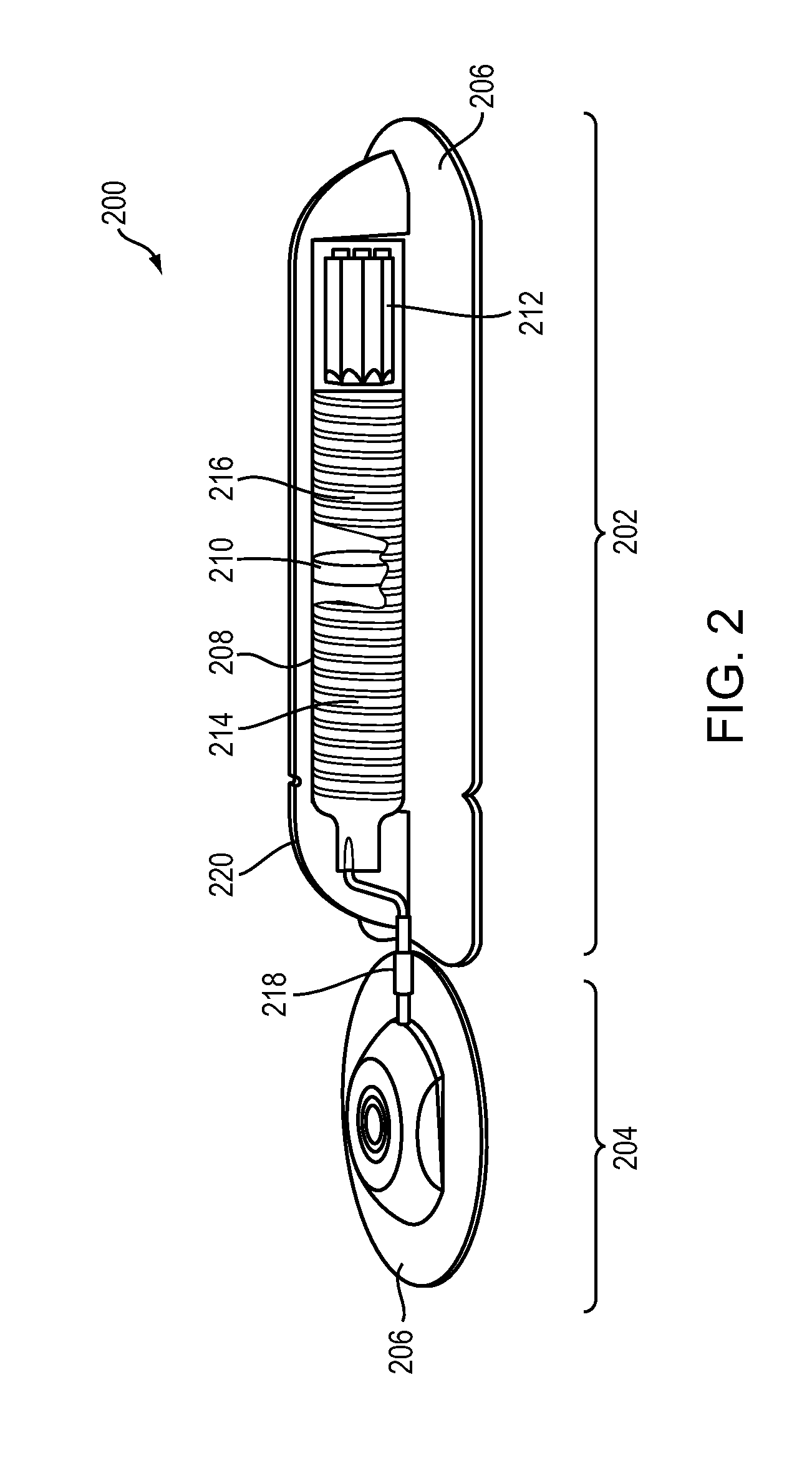
[0031]FIG. 1 illustrates, in block diagram form, the components of a drug pump device 100 in accordance with various embodiments of the present invention. In general, the pump device 100 includes a drug reservoir 102 that interfaces with a pump 104 via a displaceable member 106. The displaceable member 106 may be, for example, a piston, diaphragm, bladder, or plunger. In use, the drug reservoir 102 is filled with medication in liquid form, and pressure generated by the pump 104 moves or expands the displaceable member 106 so as to push the liquid drug out of the reservoir 102. A cannula 108 connected to an outlet of the drug reservoir 102 conducts the liquid to an infusion set 109. The cannula 108 may be made of substantially impermeable tubing, such as medical-grade plastic. The infusion set 109 may include a catheter that is fluidically connected to the cannula 108 and delivers the drug to a subcutaneous tissue region. A lancet and associated insertion mechanism may be used to dri...


PUM


Abstract

Electrolytically driven drug pump devices may be configured so as to ensure sustained contact of the electrolysis electrodes with the electrolyte, thereby improving the reliability and / or pump capacity of the devices.

Description

CROSS-REFERENCE TO RELATED APPLICATIONS[0001]This application claims priority to and the benefit of, and incorporates herein by reference in its entirety, U.S. Provisional Patent Applications No. 61 / 326,047, filed on Apr. 20, 2010, No. 61 / 367,686, filed on Jul. 26, 2010, No. 61 / 423,945, filed on Dec. 16, 2010, and No. 61 / 449,899, filed on Mar. 7, 2011.TECHNICAL FIELD[0002]The invention relates, generally, to drug pump devices, and, in various embodiments, to electrolysis-driven piston or diaphragm pump devices.BACKGROUND[0003]As patients live longer and are diagnosed with chronic and often debilitating ailments, there is an increased need for improvements to the speed, convenience, and efficacy of drug delivery. For example, many chronic conditions, including multiple sclerosis, diabetes, osteoporosis, and Alzheimer's disease, are incurable and difficult to treat with currently available therapies: oral medications have systemic side effects; injections may require a medical visit, ...

Claims


Application Information

Patent Timeline
IPC IPC(8): A61M5/145A61M37/00
CPCA61M5/16886A61M2205/3592A61M2210/0612A61M2205/3569A61M5/14526A61M2005/14204A61M5/14593A61M5/14248A61M5/1684A61M2205/3584A61M5/14276A61M2205/3523
Inventor CAFFEY, SEANLI, PO-YINGTAI, YU-CHONGHUMAYUN, MARKLAI, ALICESHIH, JASONJOURNEY, MICHELLE
Owner MINIPUMPS
Learn More