Photovoltaic module with composite materials
- Summary
- Abstract
- Description
- Claims
- Application Information
AI Technical Summary
Benefits of technology
Problems solved by technology
Method used
Image
Examples
first embodiment
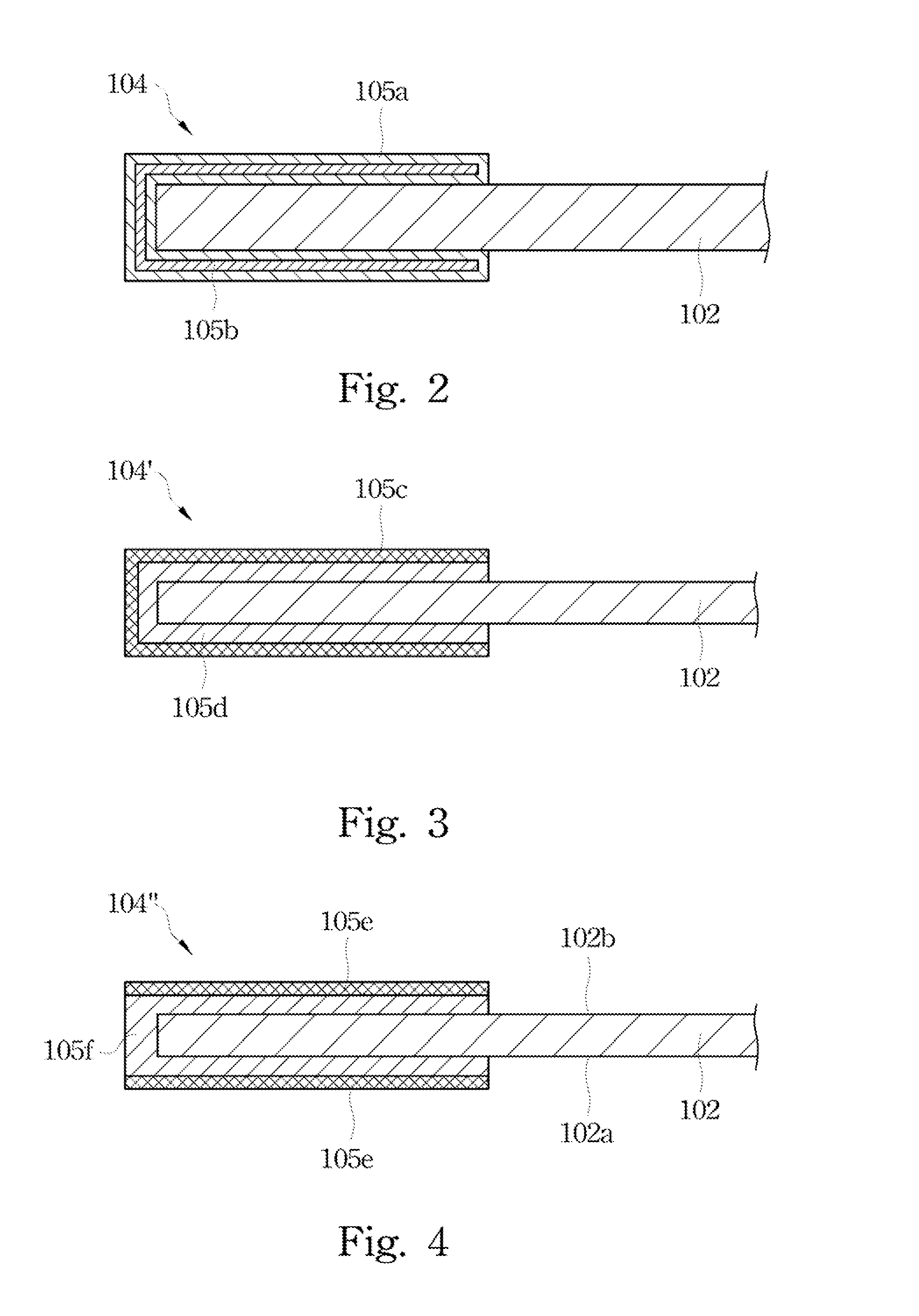
[0030]FIG. 2 illustrates a cross-sectional view of an edge portion of a photovoltaic module according to this invention. The frame 104 includes a metal portion 105a (e.g. aluminum or alloys thereof) and a composite material 105b (e.g. plastic materials mixed with glass fibers or silicone resins mixed with glass fibers). The composite material 105b is fully enclosed or sealed by the metal portion 105a. This design can be achieved by injecting a liquid phase of the composite material 105b into a hollow metal portion 105a. From this view, the metal portion 105a has its U-shaped cross-section while the composite material 105b has its U-shaped cross-section. The U-shaped cross-section of the composite material 105b is fully enclosed by the U-shaped cross-section of metal portion 105a. Therefore, the metal portion 105a is in contact with the photovoltaic panel 102, but the composite material 105b is not. In this embodiment, the composite material 105b is about 15 percent to about 25 perce...
second embodiment
[0031]FIG. 3 illustrates a cross-sectional view of an edge portion of a photovoltaic module according to this invention. The frame 104′ includes a metal portion 105c (e.g. aluminum or alloys thereof) and a composite material 105d (e.g. plastic materials mixed with glass fibers or silicone resins mixed with glass fibers). Basically, the composite material 105d is sandwiched between the metal portion 105c and the photovoltaic panel 102. This design can be achieved by injecting a liquid phase of the composite material 105d into a gap between the metal portion 105c and the photovoltaic panel 102 when the metal portion 105c and the photovoltaic panel 102 are assembled together. From this view, the metal portion 105c has a larger U-shaped cross-section while the composite material 105d has a smaller U-shaped cross-section. The U-shaped cross-section of the composite material 105d is sandwiched between the U-shaped cross-section of metal portion 105c and the photovoltaic panel 102. Therefo...
third embodiment
[0032]FIG. 4 illustrates a cross-sectional view of an edge portion of a photovoltaic module according to this invention. The frame 104″ includes a metal portion 105e (e.g. aluminum or alloys thereof) and a composite material 105f (e.g. plastic materials mixed with glass fibers or silicone resins mixed with glass fibers). This design can be achieved by injecting a liquid phase of the composite material 105f to enclose an edge of the photovoltaic panel 102, and then attach two pieces of the metal portion 105e thereon. From this view, the metal portion 105e has an upper portion and a lower portion spaced from each other while the composite material 105f has a U-shaped cross-section. An upper part of the U-shaped cross-section is sandwiched between the upper portion of the metal portion 105e and the photovoltaic panel 102 (e.g. a top surface 102b), and a lower part of the U-shaped cross-section is sandwiched between the lower portion of the metal portion 105e and the photovoltaic panel ...
PUM
 Abstract
Description
Claims
Application Information
 - R&D
- Intellectual Property
- Life Sciences
- Materials
- Tech Scout
- Unparalleled Data Quality
- Higher Quality Content
- 60% Fewer Hallucinations
Browse by: Latest US Patents, China's latest patents, Technical Efficacy Thesaurus, Application Domain, Technology Topic, Popular Technical Reports.
© 2025 PatSnap. All rights reserved.Legal|Privacy policy|Modern Slavery Act Transparency Statement|Sitemap|About US| Contact US: help@patsnap.com


