
Optical touch panel

Inactive Publication Date: 2012-02-23
NITTO DENKO CORP
View PDF3 Cites 7 Cited by
  • Summary
  • Abstract
  • Description
  • Claims
  • Application Information

AI Technical Summary

Benefits of technology

[0011]An optical touch panel is provided which permits highly accurate detection without cost increase.

Problems solved by technology

Therefore, the optical waveguides tend to have a greater size or a complicated configuration in the overall optical touch panel.
This results in higher total costs of the optical touch panel.

Method used


Image

  • Optical touch panel
  • Optical touch panel
  • Optical touch panel

Examples


example

[0070]In the following example, an optical touch panel according to the present invention was produced in the following manner by producing a light receiving optical waveguide and a light emitting optical waveguide by the photolithography process as in the embodiments described above, and combining the light receiving optical waveguide and the light emitting optical waveguide with a light emitting element array and a light source on a substrate.

Under-Cladding Layer Material and Over-Cladding Layer Material

[0071]Component (A): 35 parts by weight of bisphenoxyethanolfluorene diglycidyl ether (fluorene derivative)

Component (B): 40 parts by weight of 3′,4′-epoxycyclohexyl methyl 3,4-epoxycyclohexane carboxylate (an alicyclic epoxy resin as a diluent available under CELLOXIDE 2021P from Daicel Chemical Industries, Ltd.)

Component (C): 25 parts by weight of an alicyclic epoxy resin having a cyclohexenoxide skeleton (available under CELLOXIDE 2081 from Daicel Chemical Industries, Ltd.)

Compo...


PUM


Abstract

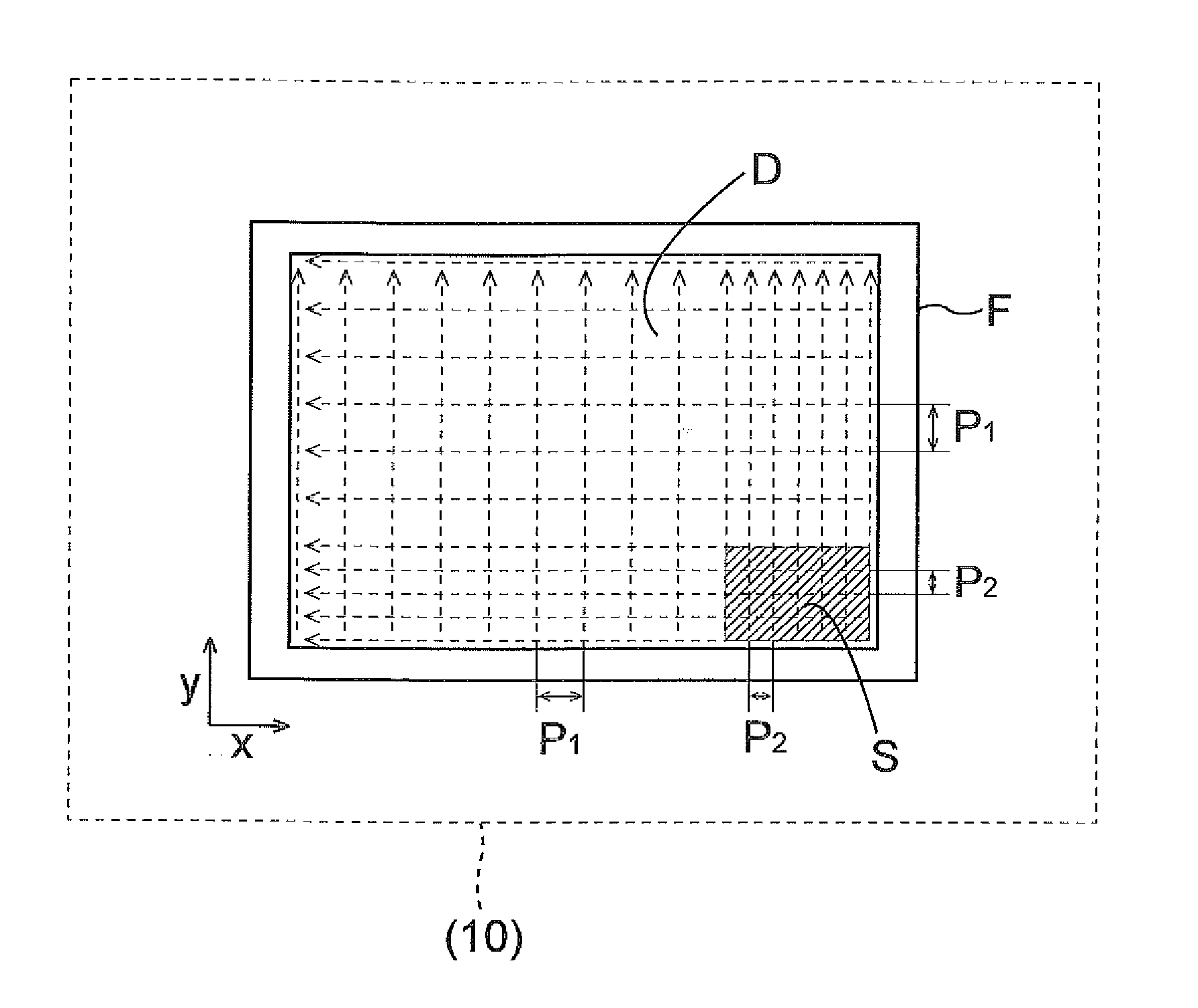
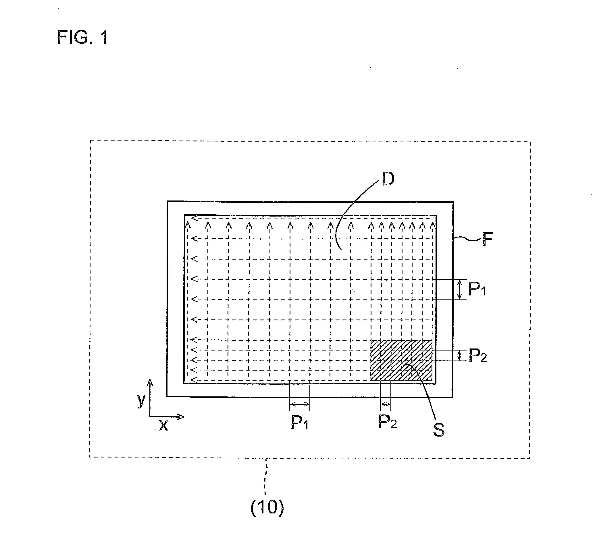
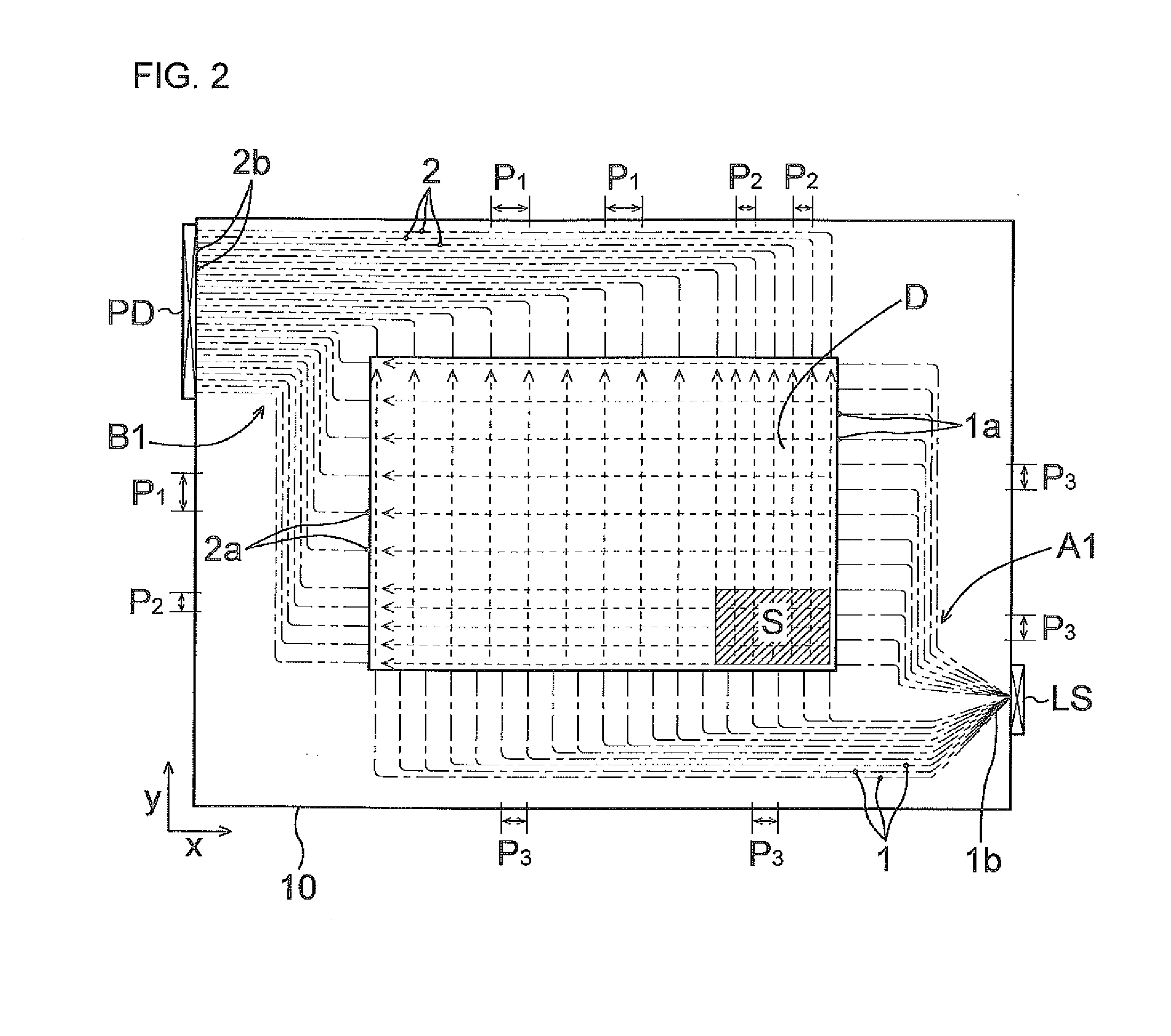
Light emitting optical waveguide cores are provided in one of opposite side portions located on opposite sides of a detection area, and light receiving optical waveguide cores are provided in the other side portion. Light beams are emitted from distal ends of the light emitting cores disposed along an inner edge of the one side portion, and received on distal ends of the light receiving cores disposed along an inner edge of the other side portion, whereby an optical lattice is defined on the detection area for detection of a touch position. The detection area includes a higher resolution detection portion defined by arranging distal ends of at least some of the light receiving cores at a pitch that is smaller than the pitch of distal ends of the other light receiving cores.

Description

BACKGROUND OF THE INVENTION[0001]1. Field of the Invention[0002]The present invention relates to an optical touch panel employing optical waveguides.[0003]2. Description of the Related Art[0004]In recent years, optical touch panels of an optical waveguide type, which are easy to maintain in the absence of electrical contacts, have come to be used instead of conventional touch panels of a resistive film type or an electrostatic capacitance coupling type. Such an optical touch panel of the optical waveguide type is designed so that light beams (generally parallel light) such as infrared beams are emitted and received by optical waveguides disposed in a peripheral portion (frame portion) of a display screen (display panel) such as a monitor or a liquid crystal display device to define an optical lattice in a detection area on the display panel. The optical touch panel is used together with information (picture patterns, icons and the like) displayed on the display screen as an input / di...

Claims


Application Information

Patent Timeline
IPC IPC(8): G06F3/042
CPCG06F3/0421
Inventor MIZUTANI, TORU
Owner NITTO DENKO CORP
Learn More