
Backlight module

a backlight module and light-emitting diodes technology, applied in the field of backlight modules, can solve the problems of increasing inevitably not being easy to dissipate heat, and the work life of light-emitting diodes in the center of the light bar is relatively short, so as to reduce the manufacturing cost of backlight modules and improve heat dissipation conditions. , the effect of increasing the proportion of usag

Active Publication Date: 2012-02-23
TCL CHINA STAR OPTOELECTRONICS TECH CO LTD
View PDF4 Cites 12 Cited by
  • Summary
  • Abstract
  • Description
  • Claims
  • Application Information

AI Technical Summary

Benefits of technology

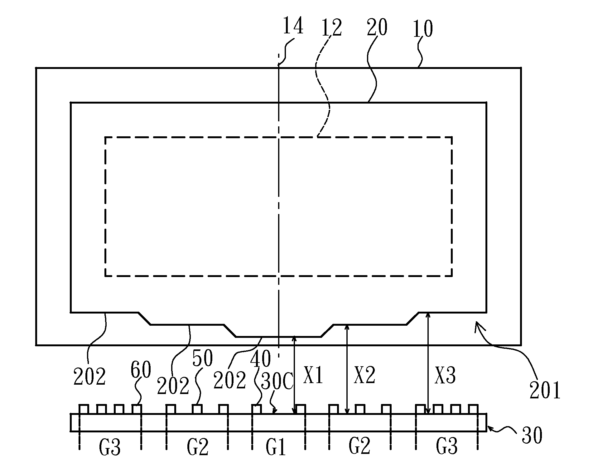
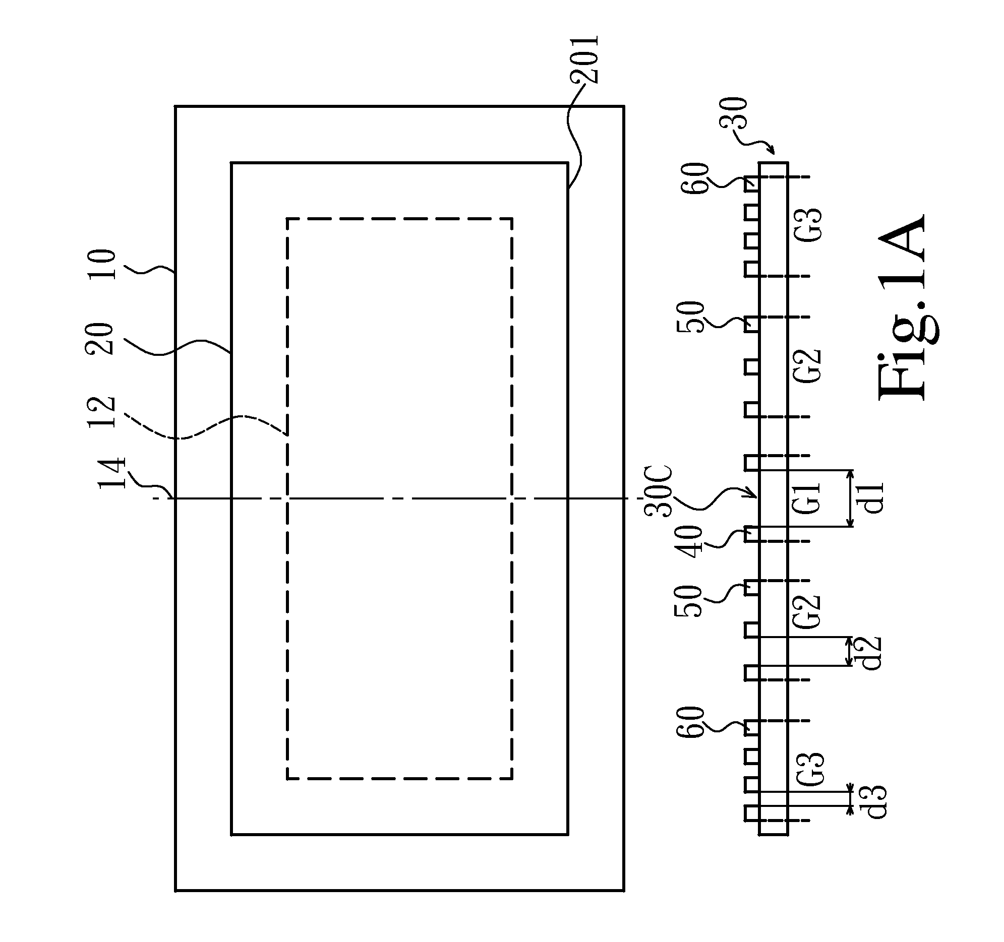
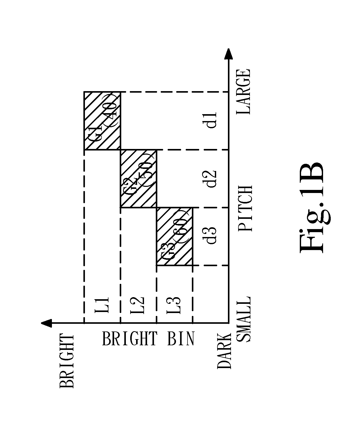
The present invention provides a backlight module for a liquid crystal display device that arranges different pitches for light-emitting diodes to improve heat-dissipating circumstances of the light-emitting diodes and increase the proportions of usage of light-emitting diodes with different bright bins, thereby reducing manufacturing costs of backlight modules. The backlight module has a light guide plate and a back board, and a plurality of light-emitting diodes divided into different groups based on their pitches. The light-emitting diodes are positioned close to the position center of the back board, and the bright bins of the light-emitting diodes are determined based on their positions relative to the display-area center line. The light-emitting diodes can be mounted on the back board or on the light guide plate. The incident surface of the light guide plate can have concave or convex surfaces, and the distance between the light group with a higher bright bin and the corresponding concave or convex surface is longer or shorter, respectively. The invention provides a direct type backlight module that arranges different pitches for light-emitting diodes to improve heat-dissipating circumstances of the light-emitting diodes and increase the proportions of usage of light-emitting diodes with different bright bins, thereby reducing manufacturing costs of backlight modules.

Problems solved by technology

Therefore, light-emitting diodes that are practically used have a low proportion of the total number of products, so that manufacturing cost of backlight module is relatively increased.
When the light bar is driven to emit lights, the light-emitting diodes in a center of the light bar inevitably will not be easy to dissipate heat compared with the light-emitting diodes in two ends of the light bar.
Since temperature difference greatly affects luminous efficiency of a light-emitting diode, phenomenon of uneven heat distribution will affect the uniformity of overall luminescence of the backlight module, and also the work life of the light-emitting diodes in the center of the light bar are relatively shorter.

Method used


Image

  • Backlight module
  • Backlight module
  • Backlight module

Examples


Embodiment Construction

[0033]The foregoing objects, features and advantages adopted by the present invention can be best understood by referring to the following detailed description of the preferred embodiments and the accompanying drawings. Furthermore, the directional terms described in the present invention, such as upper, lower, front, rear, left, right, inner, outer, side and etc., are only directions referring to the accompanying drawings, so that the used directional terms are used to describe and understand the present invention, but the present invention is not limited thereto.

[0034]With reference to FIG. 1A, FIG. 1A discloses a schematic view of a backlight module according to a first embodiment of the present invention, wherein the backlight module of the first embodiment of the present invention is an edge type backlight module. In this embodiment, the backlight module has a back board 10, a light guide plate 20, a light bar assembly 30 and a plurality of light-emitting diodes 40, 50, 60. The...


PUM

PropertyMeasurementUnit
distanceaaaaaaaaaa
heat-aaaaaaaaaa
drive poweraaaaaaaaaa

Abstract

The present invention discloses a backlight module which has a plurality of light-emitting diodes. The light-emitting diodes are divided into a plurality of light groups according to pitches between the adjacent light-emitting diodes. The light-emitting diodes with respect to a display-area center line have a position center, and the light group having the light-emitting diodes with larger pitches therebetween is in a position relatively close to the position center and is in a higher bright bin; the light group having the light-emitting diodes with smaller pitches therebetween is in a position relatively away from the position center and is in a lower bright bin. Therefore, luminous conditions of the overall light-emitting diodes tend to correspondence, and proportion of usage of light-emitting diodes in different bright bins can be increased.

Description

FIELD OF THE INVENTION[0001]The present invention relates to a backlight module, and more particularly to a backlight module that arranges light-emitting diodes thereof according to heat-dissipating conditions of the light-emitting diodes in different positions and bright bins of the light-emitting diodes.BACKGROUND OF THE INVENTION[0002]A liquid crystal display (LCD) device generally comprises a backlight module and a liquid crystal panel, and has advantages of thin, low drive power and low power consumption over other display devices and has been widely used in industries of display devices. Presently, backlight modules are mainly sorted into light-emitting-diode (LED) backlight modules and cold-cathode-fluorescent-lamp (CCFL) backlight modules. Since a light-emitting-diode backlight module has an advantage of low power consumption, hence using the light-emitting-diode backlight module to replace the cold-cathode-fluorescent-lamp backlight module is now a main development trend of...

Claims


Application Information

Patent Timeline
Patent Type & Authority Applications(United States)
IPC IPC(8): G02F1/1335
CPCG02B6/002G02B6/0068G02F1/133603G02B6/009G02B6/0073
Inventor CAO, QIANLIN, POYING
Owner TCL CHINA STAR OPTOELECTRONICS TECH CO LTD
Learn More