PDA compatible text scanner

a text scanner and pda technology, applied in the field of optical text scanning devices, can solve the problems of limiting the size of scanned documents, requiring an extra hand-held device, and not seamlessly integrated, and achieves the effects of reducing the number of scanned documents, facilitating text viewing, and increasing the signal to noise level

Inactive Publication Date: 2012-02-23
WOLF II ERICH W
View PDF6 Cites 1 Cited by
  • Summary
  • Abstract
  • Description
  • Claims
  • Application Information

AI Technical Summary

Benefits of technology

[0012]A feature of the preferred embodiment of this invention is that the text scanner assembly is constructed of optically transparent material and designed in such a way that the user can clearly view the text as it is scanned. The invention also incorporates a set of horizontal and vertical alignment marks that combine functionally with the clear view of the scanned text allowing for ease of alignment and scanning accuracy. The invention further discloses an illumination light guide that not only eases the viewing of text, but also increases the signal to noise level of the electronic image capture and subsequent character recognition process. Another feature of the invention is that it converts the scanned image of the text characters to standard byte or word digital character format in real time, for example to ASCII format, storing the digital character in memory and displaying the digital character on the PDA viewing screen. The invention incorporates the use of optical character recognition (OCR) processes in conjunction with the scan process.

Problems solved by technology

Optical wands are currently commercially available and may communicate with PDAs via an external cable, but these are not seamlessly integrated and require an extra hand-held device.
Faulkerson does not teach the on-board integration of optical scanning functions directly into a PDA.
Huang's design limits the scanned document sizes to those that can fit through the housing and otherwise suffers from similar limitations as Liao.
Tsai's invention, while not limited by the document size, suffers from some of the same general limitations as the other designs, namely that the viewing of the document is limited to a bit-mapped image of the scanned input and that there is no immediate conversion to a standard digital character format.

Method used


Image

  • PDA compatible text scanner
  • PDA compatible text scanner
  • PDA compatible text scanner

Examples


third embodiment

[0048]In a third embodiment shown in FIGS. 7A-7D, optical reader assembly 700 is shown. The optical reader assembly 700 includes optical body 710 made of clear acrylic and has two mounting tabs 742a and 742b for mounting the device on PDA unit. The mounting is accomplished by inserting the mounting tabs into matching recesses into PDA unit 100 and utilizing set screws to hold mounting tabs 742a and 742b in place. Those familiar with PDA devices will realize that the mechanical means by which the optical reader assembly attaches to the PDA unit is dependent upon the specific geometry of the PDA unit and that the invention may easily encompass other means of attachment. For example, in other embodiments it may be beneficial to include a spring-loaded ball-and-detent attachment mechanism or a molded plastic form that snaps to the body of the PDA to allow for rapid and easy removal of the optical reader assembly when it is not in use.

[0049]Optical reader assembly 700 includes an optical...

fourth embodiment

[0060]In a fourth embodiment shown in FIG. 8, optical reader assembly 800 is shown. The optical reader assembly 800 is made of clear acrylic and has two mounting tabs 842a and 842b for mounting the device on PDA unit 100. The mounting is accomplished by inserting the mounting tabs into matching recesses into PDA unit 100 and utilizing set screws to hold mounting tabs 842 in place. Those familiar with PDA devices will realize that the mechanical means by which the optical reader assembly attaches to the PDA unit is dependent upon the specific geometry of the PDA unit and that the invention may easily encompass other means of attachment. For example, in other embodiments it may be beneficial to include a spring-loaded ball-and-detent attachment mechanism or a molded plastic form that snaps to the body of the PDA to allow for rapid and easy removal of the optical reader assembly when it is not in use.

[0061]Optical reader assembly 800 includes an optical body made of clear acrylic mater...

fifth embodiment

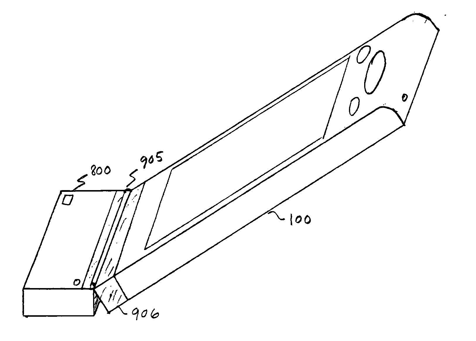
[0069]In a fifth embodiment shown in FIGS. 9 and 10A-10C, optical reader assembly 800 is rotatably attached to PDA unit 100 by a hinge 905 attached to the optical reader assembly and a mounting assembly 906. Mounting assembly 906 includes a frame and a cavity 908. Mounting assembly 906 is attached to PDA unit 100 by a releasable friction fit between cavity 907 and PDA Unit 100. Optical reader assembly 800 is electrically connected to flexible connector 910. Flexible connector 910 is electrically connected to connector 850. Connector 850 is, in turn, connected to the PDA. Optical reader assembly 800 includes a pocket 930 to store excess flexible connector material.

[0070]In use, hinge 905 enables the PDA to be held at a different angle than the optical reader assembly. The angle allows a more comfortable and natural angle for scanning lengthy text subjects and therefore accommodates the user.

[0071]The electronic architecture of the invention is shown in FIG. 5. PDA unit 100 includes a...


PUM


Abstract

An optical text scanning device compatible with a small handheld computer such as a personal digital assistant (PDA). The scanning device allows for a clear view of the text that is scanned simultaneous to the scanning process so that the operator can continuously align the device to the text. The scanned images of the text are converted in real-time to standard byte or word characters for subsequent display on the computer's viewing screen. The operator can quickly verify the accuracy of the conversion by comparing the displayed character with the actual character of text on the surface that is being scanned. Scanned text characters are stored in standard digital text files for ease of manipulation.

Description

CROSS-REFERENCE TO RELATED APPLICATIONS[0001]This application is a continuation-in-part claiming priority to U.S. patent application Ser. No. 12 / 070,803 filed Feb. 21, 2008 which was a continuation-in-part claiming priority to U.S. patent application Ser. No. 11 / 156,814 filed Jun. 17, 2005, now U.S. Pat. No. 7,364,077.TECHNICAL FIELD OF THE INVENTION[0002]The invention relates to an optical text scanning device integrated with a small handheld computer such as a personal digital assistant (PDA). In particular, it teaches hardware and software concepts that allow simultaneous optical viewing of the text as it is scanned and real-time conversion of the scanned images to a standard text character stream for subsequent display on a viewing screen.BACKGROUND OF THE INVENTION[0003]The small handheld computer or personal digital assistant (PDA) has become a popular tool in the business world and more recently in personal communications. These devices have incorporated wireless functions, c...

Claims


Application Information

Patent Timeline
Patent Type & Authority Applications(United States)
IPC IPC(8): H04N1/04G06V10/12G06V10/147G06V30/10
CPCG06F1/1626G06K2209/01G06F1/1686H04N1/00236H04N1/00241H04N1/00331H04N1/0044H04N1/03H04N1/0301H04N1/0303H04N1/0305H04N1/107H04N1/195H04N2201/001H04N2201/0051H04N2201/0056H04N2201/0063H04N2201/0068H04N2201/0081H04N2201/0084H04N2201/0096H04N2201/043H04N2201/0452G06K9/00919G06K9/209G06K9/24G06F1/1632G06V40/63G06V10/12G06V10/147G06V30/10
Inventor WOLF, II, ERICH W.
Owner WOLF II ERICH W
Why Eureka
Try Eureka