Coupling assembly for transferring electrical energy

Active Publication Date: 2017-06-15
EXPLICATION AUTOMATION LLC
View PDF5 Cites 35 Cited by
  • Summary
  • Abstract
  • Description
  • Claims
  • Application Information

AI Technical Summary

Benefits of technology

[0020]In an advanced embodiment of the invention, independent intelligence is incorporated into the Connector in the form of a microprocessor and microcontroller/switchgear, so that the Connector is capable of detecting whether the load side of the Unit is grounded negatively or positively. Such detection allows the Connector to engage the load with a DC charge utilizing first the pole with the correct polarity and then second the pole with the opposite polarity. For example, in an EV that is grounded with the negative terminal, the Connector

Problems solved by technology

The configuration of the connector and the receptacle require an individual to be able to (a) align the components which, even with alignment guides, may be d

Method used


Image

  • Coupling assembly for transferring electrical energy
  • Coupling assembly for transferring electrical energy
  • Coupling assembly for transferring electrical energy

Examples


Embodiment Construction

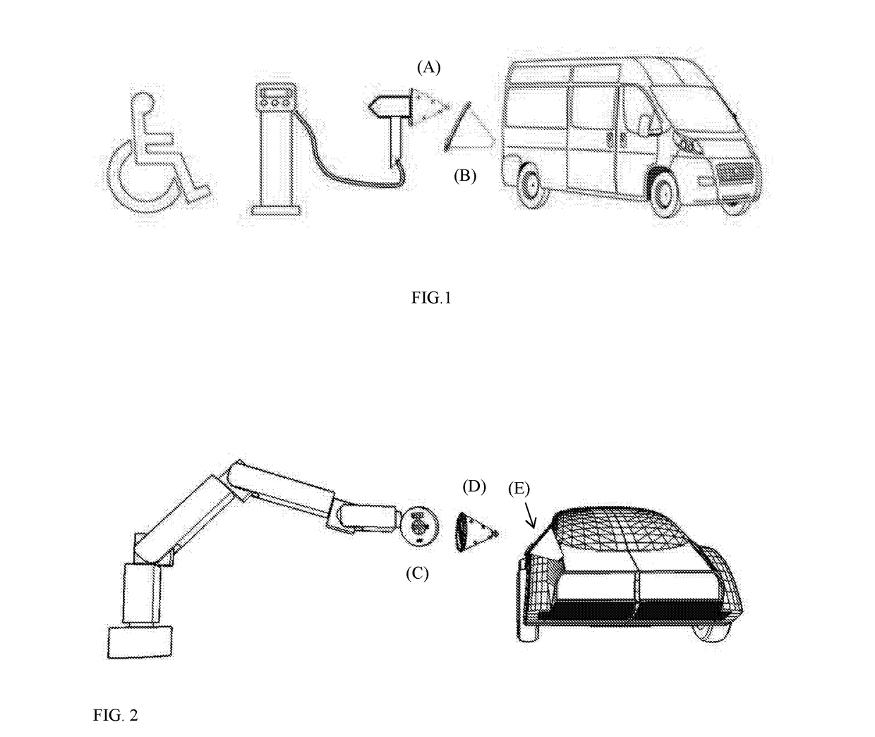
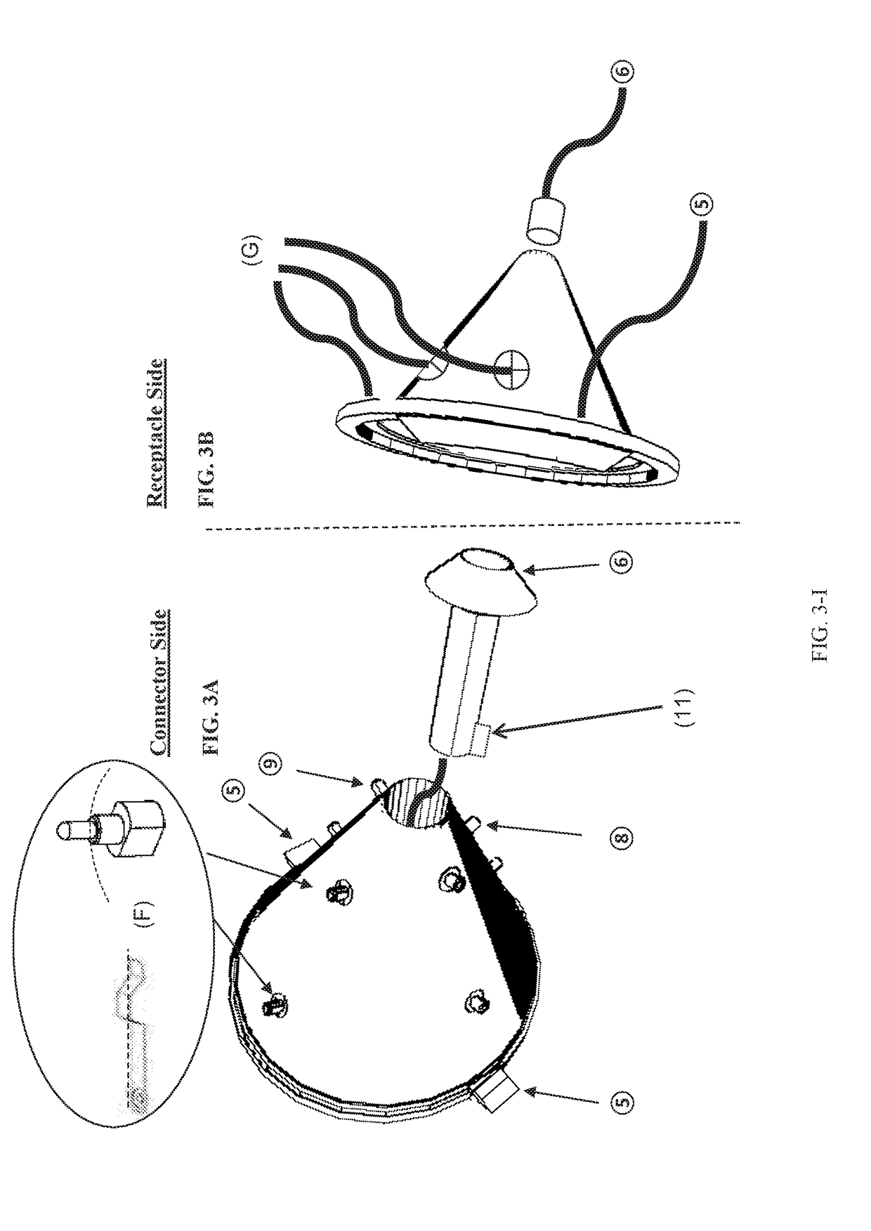
[0041]The new system of coupling a Connector with its respective Receptacle, by means of utilizing an exterior shape of a solid geometric form to facilitate the alignment of the Unit components, will lessen the degree of physical exertion required to engage in the transfer of energy between a source and a specified load. Through application of the invention, physically challenged individuals or lightweight equipment will be capable of engaging in charging sessions where they would otherwise be taxed or incapable of doing so.

[0042]Further, the invention is a capable of deployment on a universal basis and will facilitate the use of currently existing charging infrastructure through the use of “custom-to-standard” adapters.

[0043]The invention overcomes the limitations and weaknesses of the current art through the following:[0044]1. The self-aligning Connector and accompanying Receptacle, which together form a Unit, utilize an exterior shape of a solid geometric form which enables the s...


PUM


Abstract

A self-aligning motor assisted electrical Connector with exterior shape of a solid geometric form and accompanying complementary Receptacle (which when placed together form a Unit) that reduces the conventionally necessary exertion of force and dexterity requirements placed upon individuals and automated equipment, for use in transferring energy between a primary charging source and an electric vehicle or an energy storage device, such as a battery or battery bank; provided, however, that a transfer of energy may also occur by engaging such Unit so that the electric vehicle, battery or battery bank becomes the primary source of energy which transfers electric power through the Unit to an ultimate load.

Description

FIELD OF THE INVENTION[0001]The concept of this invention is to provide a self-aligning motor assisted electrical Connector with exterior shape of a solid geometric form and accompanying complementary Receptacle (which when placed together form a Unit) that reduces the conventionally necessary exertion of three and dexterity requirements placed upon individuals and automated equipment, for use in transferring energy between a primary charging source and an electric vehicle or an energy storage device, such as a battery or battery bank; provided, however, that a transfer of energy may also occur by engaging such Unit so that the electric vehicle, battery or battery hank becomes the primary source of energy which transfers electric power through the Unit to an ultimate load.BACKGROUND OF THE INVENTION[0002]Within the past decade there has been an increased awareness of the impact that carbon dioxide and methane emissions have on the earth's environment, and society has responded to th...

Claims


Application Information

Patent Timeline
IPC IPC(8): B60L11/18H01R13/631H02J7/00
CPCB60L11/1818B60L11/1827H01R2201/26H01R13/631H02J7/0027H01R13/635H01R13/639H01R13/71Y02T90/14H01R24/38H01R24/58B60L53/16B60L53/30B60L53/35B60L53/11B60L58/21B60L53/305Y02T10/70Y02T10/7072Y02T90/12Y02T90/16H01R24/00
Inventor DUNGER, MARK S.DUNGER, JAMES F.
Owner EXPLICATION AUTOMATION LLC
Why Eureka
Try Eureka