Electric storage device

a technology of electric storage and storage device, which is applied in the direction of cell components, flat cell grouping, sustainable manufacturing/processing, etc., can solve the problems of low resistance of lithium ion capacitor, high internal resistance, and inability to easily reduce resistance, so as to achieve short time and reduce resistance

Inactive Publication Date: 2012-02-23
TOKIN CORP
View PDF0 Cites 55 Cited by
  • Summary
  • Abstract
  • Description
  • Claims
  • Application Information

AI Technical Summary

Benefits of technology

[0022]According to the present invention, it is possible to provide an electric storage device whose

Problems solved by technology

However, it is very difficult because of its structure.
However, the lithium-ion secondary battery suffers from a problem that the in

Method used


Image

  • Electric storage device
  • Electric storage device
  • Electric storage device

Examples


example 1

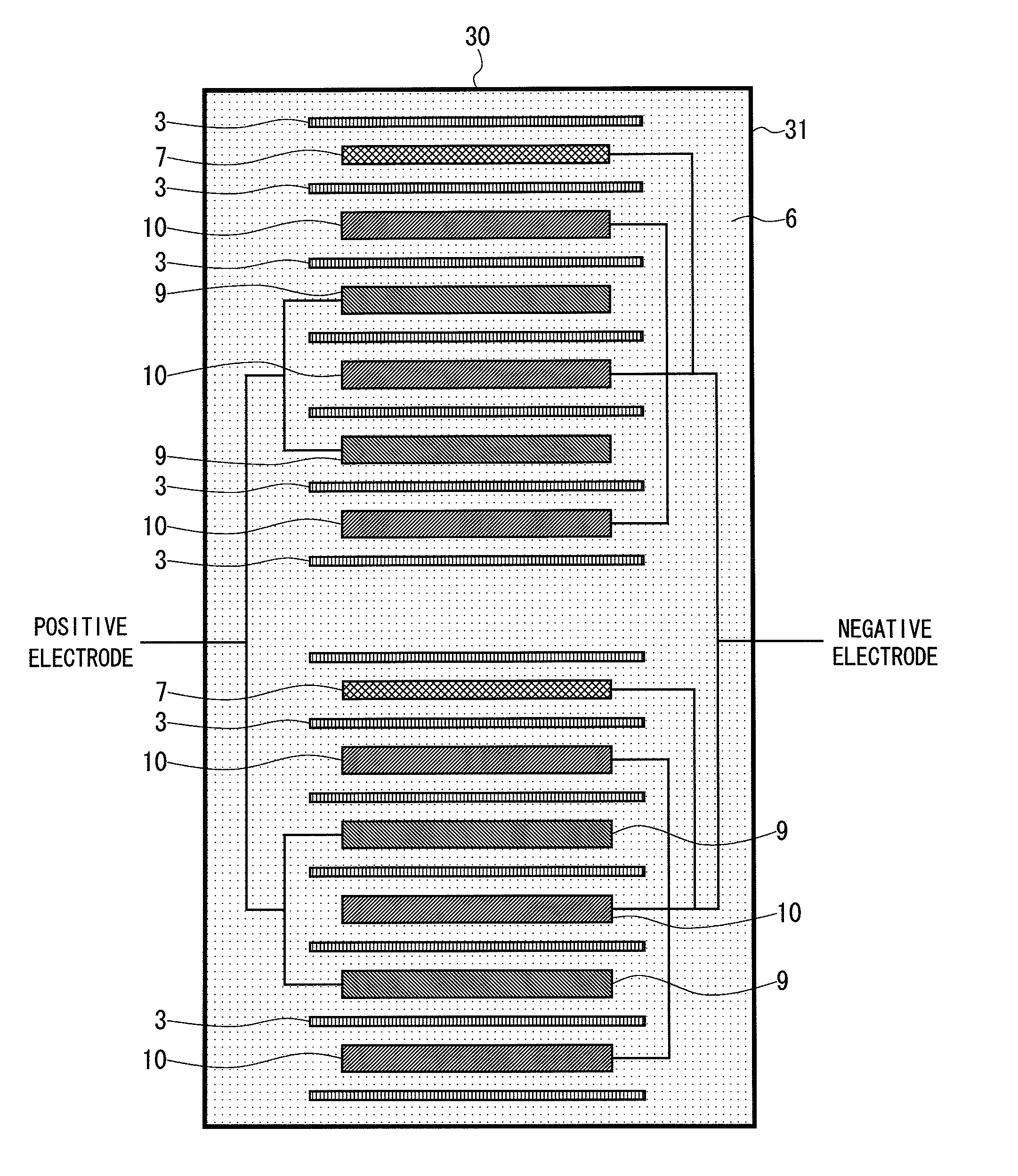
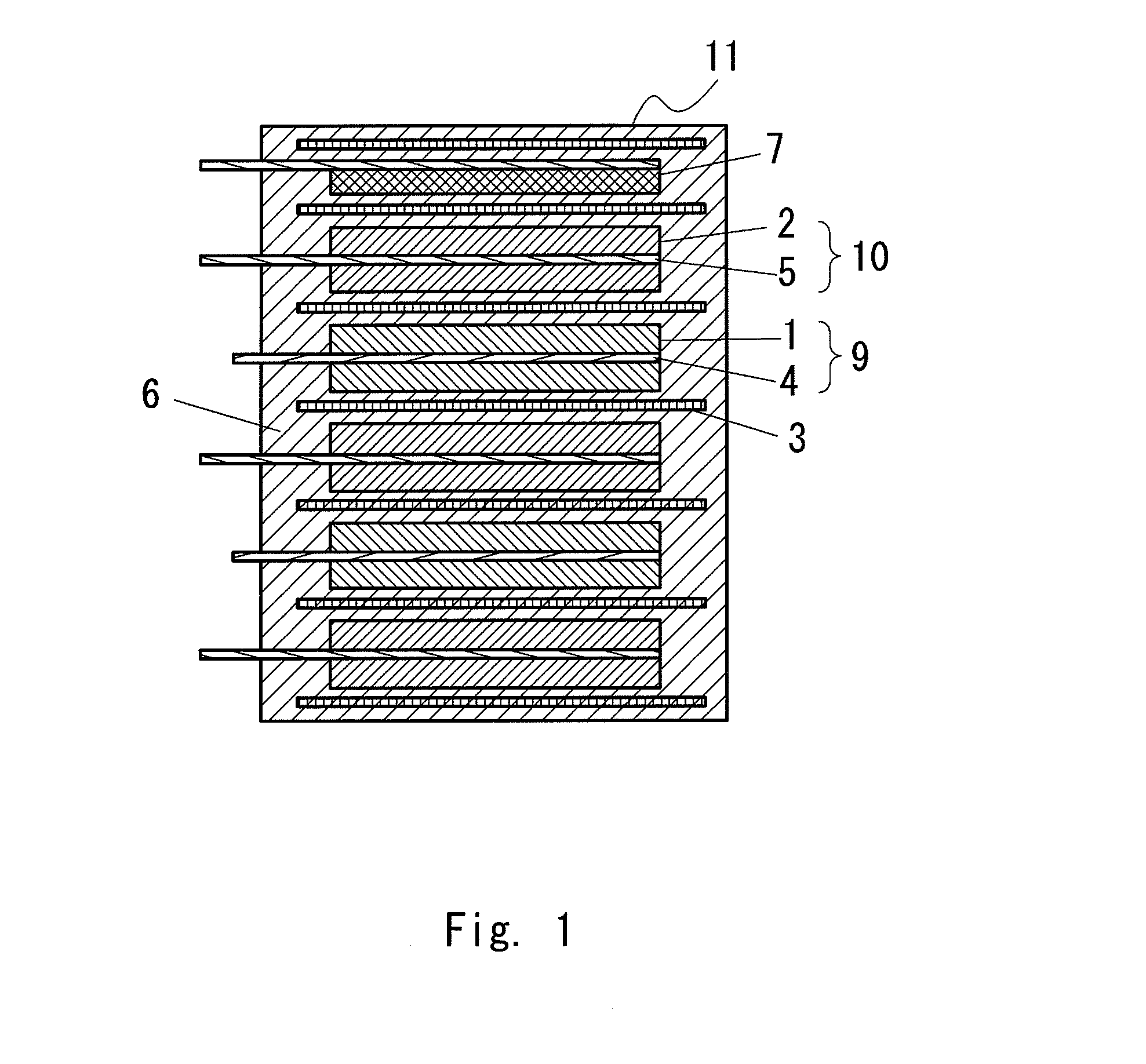
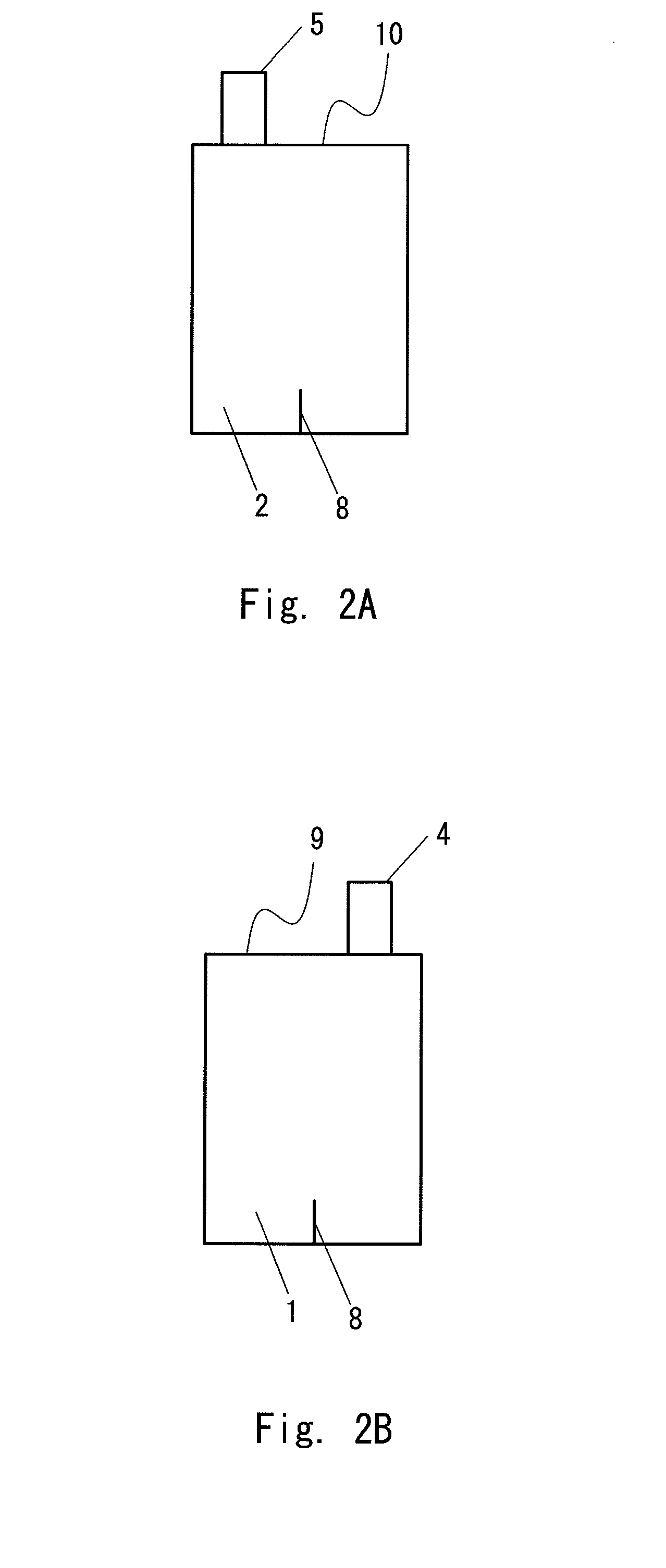
[0077]FIGS. 2A and 2B slow a first configuration example of an electric storage device according to the present invention. In particular, FIG. 2A is a top view of a negative-electrode sheet and FIG. 2B is a top view of a positive-electrode sheet. In the negative-electrode sheet 10, a coating of a negative-electrode active material layer 2 was applied in a rectangular shape to the negative-electrode charge collector 5 formed from a foil. Further, in the positive-electrode sheet 9, a coating of a positive-electrode active material layer 1 was applied in a rectangular shape to the positive-electrode charge collector 4 formed from a foil. A single cut 8 having a length of 14 mm was formed, in each sheet, on the side opposite to the side from which the negative-electrode charge collector 5 or the positive-electrode charge collector 4 protruded and was exposed.

[0078]Mixed powder comprising 92 wt.pts. of powder of a phenol-based activated carbon having a specific surface of 1500 m2 / g, whic...

example 2

[0086]FIGS. 3A and 3B show a second configuration example of an electric storage device according to the present invention. In particular, FIG. 3A is a top view of a negative-electrode sheet and FIG. 3B is a top view of a positive-electrode sheet. In the negative-electrode sheet 10, a coating of a negative-electrode active material layer 2 was applied in a rectangular shape to the negative-electrode charge collector 5 formed from a foil. Further, in the positive-electrode sheet 9, a coating of a positive-electrode active material layer 1 was applied in a rectangular shape to the positive-electrode charge collector 4 formed from a foil. Two cuts 8 having a length of 35 mm were formed with an interval of 10 mm, in each sheet, on the side opposite to the side from which the negative-electrode charge collector 5 or the positive-electrode charge collector 4 protruded and was exposed.

[0087]Lithium ion capacitors were manufactured in a similar manner to that of Example 1 except that the tw...

example 3

[0090]FIGS. 4A and 4B show a third configuration example of an electric storage device according to the present invention. In particular, FIG. 4A is a top view of a negative-electrode sheet and FIG. 4B is a top view of a positive-electrode sheet. In the negative-electrode sheet 10, a coating of a negative-electrode active material layer 2 was applied in a rectangular shape to the negative-electrode charge collector 5 formed from a foil. Further, in the positive-electrode sheet 9, a coating of a positive-electrode active material layer 1 was applied in a rectangular shape to the positive-electrode charge collector 4 formed from a foil. Five cuts 8 having a length of 35 mm were formed with intervals of 5 mm, in each sheet, on the side opposite to the side from which the negative-electrode charge collector or the positive-electrode charge collector 4 protruded and was exposed.

[0091]Lithium ion capacitors were manufactured in a similar manner to that of Example 1 except that the five cu...


PUM

PropertyMeasurementUnit
Lengthaaaaaaaaaa
Lengthaaaaaaaaaa
Fractionaaaaaaaaaa

Abstract

To provide an electric storage device whose negative electrode can be doped with lithium ions in a short time and whose resistance can be lowered. An electric storage device including a unit that is obtained by alternately stacking a positive-electrode sheet 9 and a negative-electrode sheet 10 with a separator 3 interposed therebetween, the positive electrode sheet 9 including a positive-electrode active material layer 1 and a positive-electrode charge collector 4, and the negative electrode sheet 10 including a negative-electrode active material layer 2 and a negative-electrode charge collector 5, in which a foil, an etching foil, or a porous lath foil is used as the positive-electrode charge collector 4 and the negative-electrode charge collector 5, a cut is made in a coating area of the positive-electrode active material layer 1 and the negative-electrode active material layer 2, and a lithium supply source is disposed so as to be opposed to the negative electrode sheet 10 of the unit.

Description

TECHNICAL FIELD[0001]The present invention relates to an electric storage device that is a hybrid capacitor or a secondary battery.BACKGROUND ART[0002]In consideration for the oil reserve problem and for the ecology such as the global warming, electric storage devices have been studied as an energy source for driving a motor used in electric vehicles and the like or as the key device of energy regenerative systems. Further, the applications to various new purposes such as applications to uninterrupted power supply systems, wind power generators, and solar power generators have been also studied. Accordingly, electric storage devices have been highly expected to be the next-generation devices.[0003]In recent years, it has been desired to further increase the energy density of electric storage devices and to decrease their resistance in the applications to energy resources and energy regeneration systems.[0004]In general, electric double-layer capacitors are categorized into an aqueou...

Claims


Application Information

Patent Timeline
IPC IPC(8): H01M4/13H01G4/30H01M4/139H01G9/058H01M10/04H01G11/06H01G11/12H01G11/26H01G11/52H01G11/70H01G11/72H01G11/86
CPCH01G11/12Y10T29/49108H01G11/52H01G11/70H01G11/72H01G11/86H01M4/13H01M4/661H01M4/70H01M4/80H01M10/052H01M10/0525H01M10/0585Y02E60/122Y02T10/7011Y02T10/7022H01G11/06Y02E60/13Y10T29/417H01G11/26Y02E60/10Y02T10/70Y02P70/50H01G11/22H01G11/66
Inventor SEKI, DAISUKEHATO, YUKINORIOOYA, MASAKOYOSHIDA, KATSUHIROMIYAGAWA, RISAMAEDA, KOUJI
Owner TOKIN CORP
Why Eureka
Try Eureka