
Solar Powered Active Roof Ridge Vent

a solar energy and active technology, applied in ventilation systems, lighting and heating apparatus, heating types, etc., can solve the problems of insufficient aesthetics, difficulty in installation, and increase the energy cost of the home owner

Inactive Publication Date: 2012-02-23
ESKOLA III EDWARD WALFRED
View PDF11 Cites 25 Cited by
  • Summary
  • Abstract
  • Description
  • Claims
  • Application Information

AI Technical Summary

Benefits of technology

[0012]The preferred embodiment of this invention employs a panel, referred to as the main panel, replicating the look of a passive ridge vent panel, having a laterally flexible section but with edge extremities that enable sealing to the roofline and to adjacent ridge mounted panels. The panel has holes cut at the apex at which axial fans are in

Problems solved by technology

The warm air in the attic then drives up the temperature of the home or for homes with air conditioners the cooling load on the air conditioning system of the home, thus increasing energy cost to the home owner.
The limitations of the passive device are that they use natural convection and thus do not drive down attic temperatures as much as an active system, which may take advantage of natural convection but also augment the air flow with a powered device.
Active solutions currently proposed, on the market and in prior art have several chief impairments limiting their effectiveness and ubiquitousness.
The main impairments of prior art outlined here include difficulty in installation, aesthetic inadequacy, common roof type incompatibility, and cost.
Other miscellaneous inadequacies discussed include inefficiency and debris ingestion.
A critical driving factor in determining the implementation of active attic ventilation by contractors, homebuilders or the average home owner / do-it-yourselfer is the difficulty of installation and complexity of installation of the active device.
Accessing the ridge area of many attics from the inside can be very difficult due to reach and interior structural member interference.
The installation factors described are difficult, overly complicated and require some carpentry or electrician expertise.
The complexity involved with installation of existing prior art also deters contractors and homebuilders from use.
Many active solutions are also not aesthetically pleasing, forming a large protuberance on the acreage areas of a rooftop's decking.
Such protuberances limit the device's installation locations to positions on the rooftop out of view of the front the home or building.
Wherever installed, they create discontinuity in the profile of the home or buildings roofline which diminishes the aesthetic appeal of the home.
Some of the active attic ridge ventilation solutions in prior art are not compatible with roofs with a ridge beam or ridge board.
Some proposed active solutions are not attractive to the consumer due to their expense.
The cost of proposed solutions is in some cases relatively high due to complexities in the design of the device and in the cost associated with installation of the device (previously discussed).
For example, some prior art includes complex electrical controllers for managing the active devices.
Such control may marginally enhance efficiency of the device but consequently drives up the cost of the device to the consumer.
Higher initial device cost makes the device less attractive to the consumer.
The added complexity also increases the power demands of the device, prohibiting the effective use of a solar panel as the sole source powering the device.
For prior proposed solutions involving impellers or other active devices placed at the ridge vent outlet, difficulty with debris ingestion, exposure of moving parts to the elements, inherent inefficiencies with impeller fan designs driving the need to provide grid derived power to the device and impeller device size limitations due to positioning are all challenges present.

Method used


Image

  • Solar Powered Active Roof Ridge Vent
  • Solar Powered Active Roof Ridge Vent
  • Solar Powered Active Roof Ridge Vent

Examples


embodiment

Preferred Embodiment

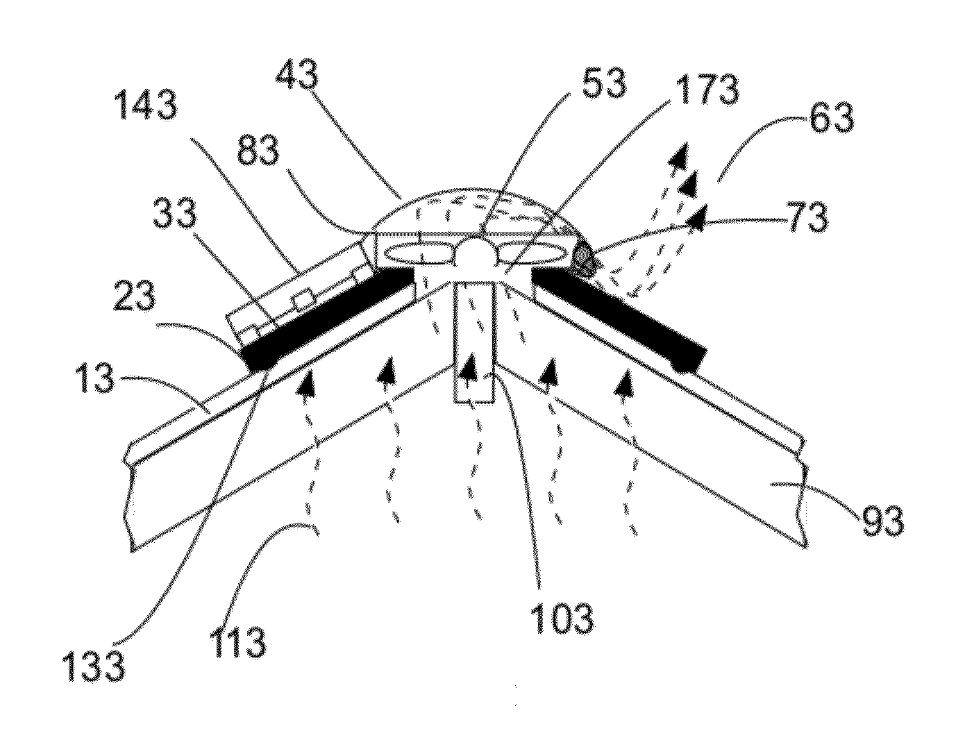
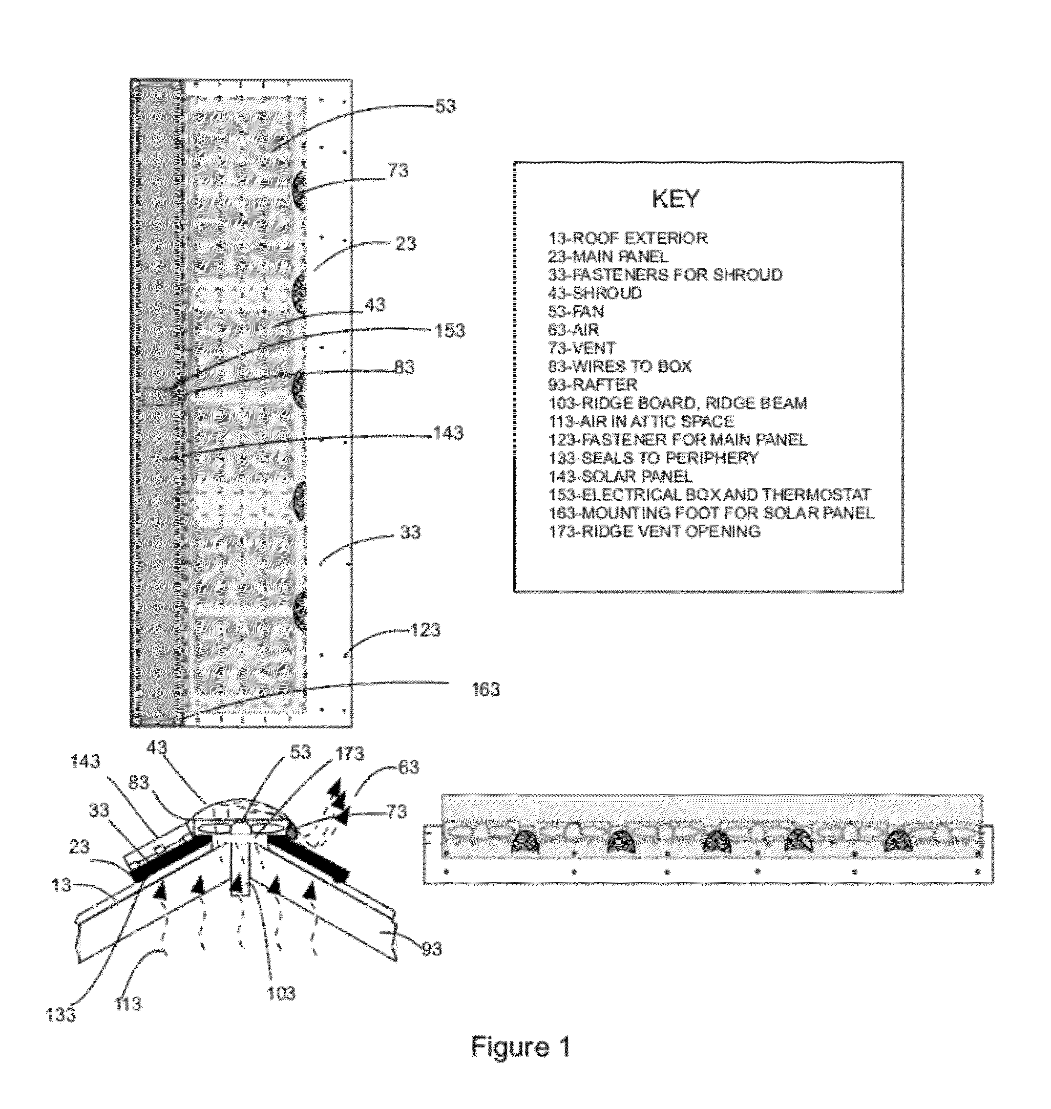
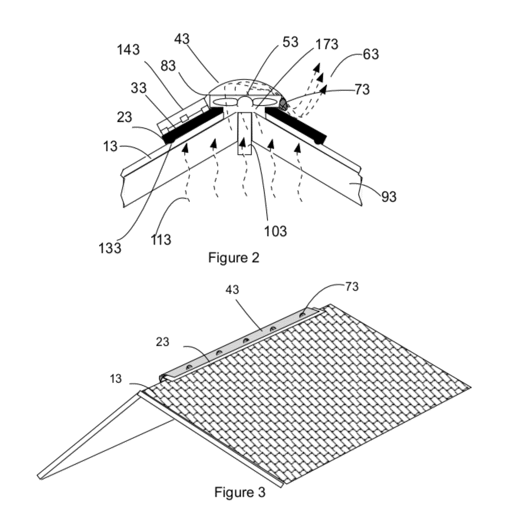
[0020]FIG. 1 shows the ventilation apparatus according to the preferred embodiment of the invention. As shown, the apparatus includes a rectangular panel, the main panel, (23) with a laterally flexible section allowing the panel to be installed over, to cover and seal the apex of a roof in which the upper section of the decking has been removed to allow air flow through the ridge. The laterally flexible panel is sealed along its edges using standard flexible sealing material to promote airflow through the active portion of the device (133). Holes are cut in to the laterally flexible panel's central section to allow for the installation of a series of axial fans (53) enabling them to extract air (113,63) from beneath the panel and exhaust it into the panels upper cavity formed by a flexible shroud (43). The fans are held in position on the main panel with standard fasteners. The flexible shroud (43) forms a cavity above the flexible main panel in which the hot exh...


PUM


Abstract

A solar powered roof ridge vent apparatus is provided for actively conducting warm air from an attic space of a home or building to the ambient environment. The roof ridge vent apparatus includes a series of electrically powered axial fans fastened to openings formed in a laterally flexible main panel which is installed at the ridge opening of a roof on a home or building. The laterally flexible main panel seals to the roofline. The series of fans are protected from the elements by a shroud. The shroud is fastened to the laterally flexible main panel and forms a cavity surrounding the fans in which the fan drawn air is first introduced prior to passing through a vent to the ambient environment. The fans are powered using electricity generated by a solar panel, which is mounted to the main panel. A thermostat is employed to deactivate the electrical fans at lower ambient temperatures when attic ventilation is undesirable. The apparatus can be installed as a single unit to the exterior of the home.

Description

CROSS-REFERENCE TO RELATED APPLICATIONS: Not ApplicableFEDERALLY SPONSORED RESEARCH OR DEVELOPMENT: Not ApplicableSEQUENCE LISTING OR PROGRAM: Not ApplicableBACKGROUND[0001]1. Field[0002]This invention relates to roof vents, and more specifically to roof ridge vents.[0003]2. Prior Art[0004]In areas of warmer climates, the attic spaces of homes or buildings tend to accumulate air much warmer than the ambient environment. The warm air in the attic then drives up the temperature of the home or for homes with air conditioners the cooling load on the air conditioning system of the home, thus increasing energy cost to the home owner. Attic ventilation is known to play an important role in reducing the heat transferred to the interior volume of the home especially in homes with inadequate attic insulation. Many techniques, systems, and devices, some passive, some active, have been developed for ventilation of the attic spaces of homes. Passive systems include passive attic vents, ridge ven...

Claims


Application Information

Patent Timeline
IPC IPC(8): F24F7/06F24F7/02
CPCF24F7/025Y02B10/24F24F2005/0064Y02A30/272Y02B10/20
Inventor ESKOLA, III, EDWARD WALFRED
Owner ESKOLA III EDWARD WALFRED
Learn More