
Oilfield applications for distributed vibration sensing technology

a technology of distributed vibration and sensing technology, applied in seismology for waterlogging, instruments, borehole/well accessories, etc., can solve the problems of significant amount of time and effort, and achieve the effect of effectively monitoring fluid movement, maintaining and increasing reservoir productivity, and operating efficiency

Inactive Publication Date: 2012-02-23
SCHLUMBERGER TECH CORP
View PDF14 Cites 71 Cited by
  • Summary
  • Abstract
  • Description
  • Claims
  • Application Information

AI Technical Summary

Benefits of technology

[0009]As stated above, the understanding of fluid flow is critical to operational efficiency in the oil and gas industry. A significant amount of time and effort is dedicated to understanding what fluid or gas is flowing from which zones within a well. Additionally, the understanding of fluid flow is critical throughout the hydrocarbon production system including related surface facilities. The same holds true for fluids and gases which are injected into subsurface reservoirs for the purpose of maintaining and increasing reservoir productivity. It is just as critical to understand the flow of these fluids in the surface pipeline network and subsurface.
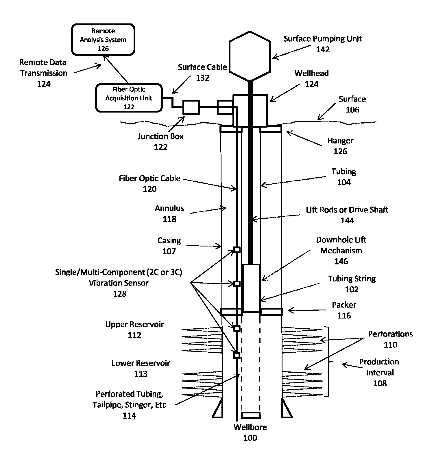
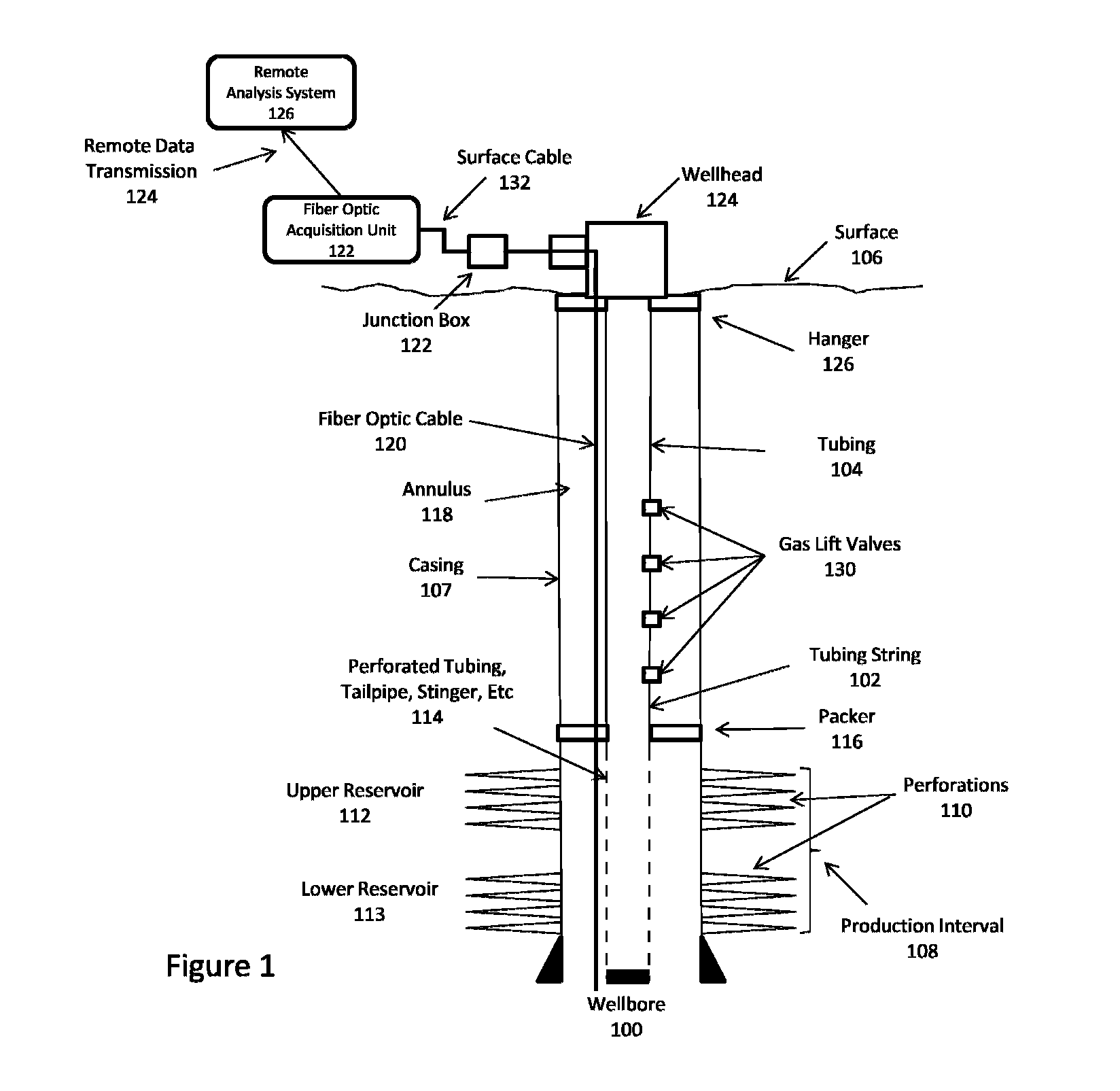
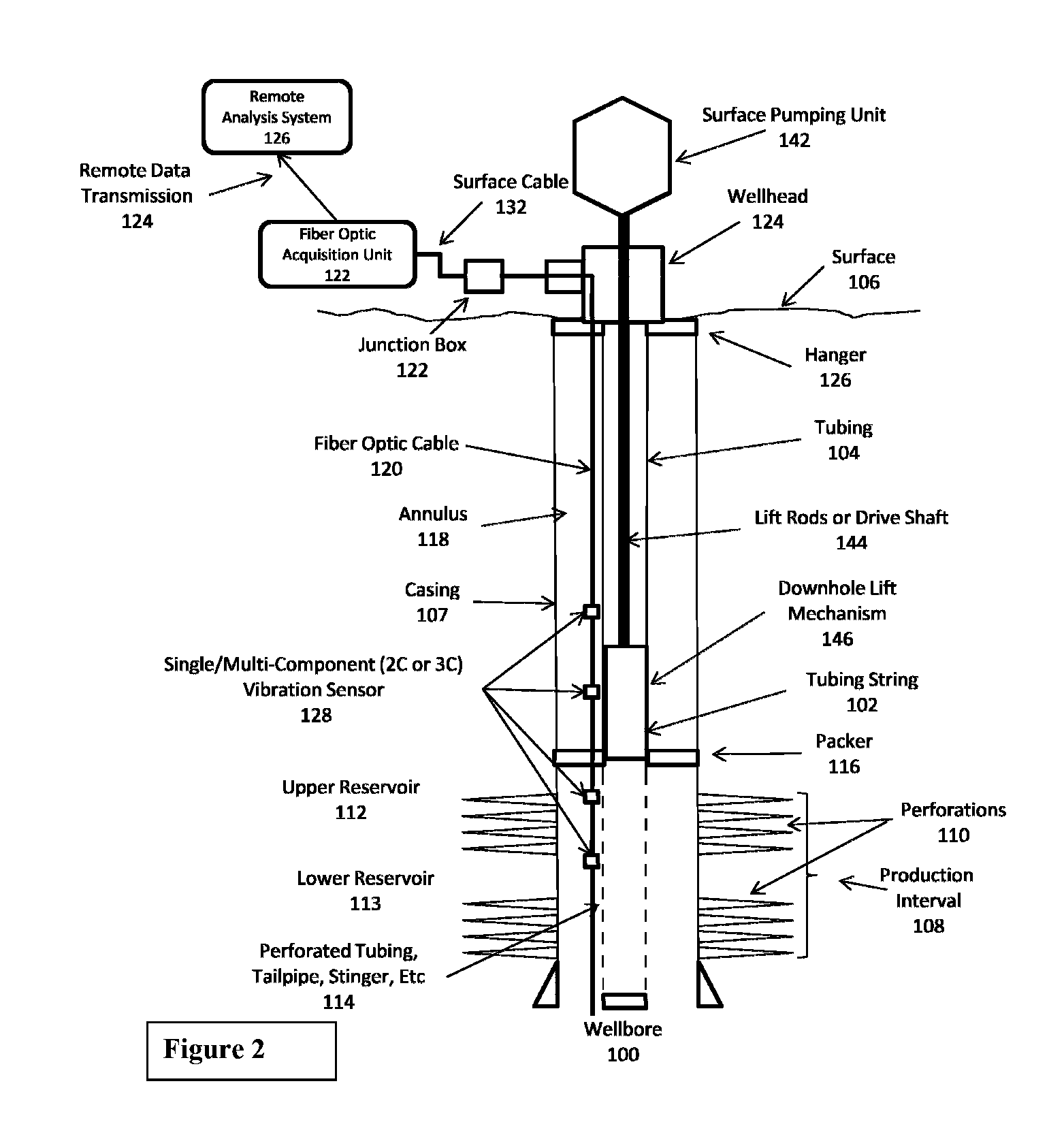
[0010]Distributed vibration measurements using fiber optic technology whereby the fiber is installed in or near the production system, whether in the surface facilities of in down-hole conditions, offers the opportunity to effectively monitor fluid movement and make a determination of the fluid velocity. Vibration, either naturally occurring or induced through mechanical means, offers the ability to characterize fluid flow qualitatively and quantitatively depending on the fluid type and fluid properties. This invention is

Problems solved by technology

A significant amount of time and effort is dedicated to understanding what fluid or gas is flowing from which zones within a well.
A significant amount of time and effort is dedicated to monitoring and maintaining production equipment within a well and in the production and injection systems.

Method used


Image

  • Oilfield applications for distributed vibration sensing technology
  • Oilfield applications for distributed vibration sensing technology
  • Oilfield applications for distributed vibration sensing technology

Examples


Embodiment Construction

[0021]In the following description, numerous details are set forth to provide an understanding of the present invention. However, it will be understood by those skilled in the art that the present invention may be practiced without these details and that numerous variations or modifications from the described embodiments may be possible.

[0022]In the specification and appended claims: the terms “connect”, “connection”, “connected”, “in connection with”, and “connecting” are used to mean “in direct connection with” or “in connection with via one or more elements”; and the term “set” is used to mean “one element” or “more than one element”. Further, the terms “couple”, “coupling”, “coupled”, “coupled together”, and “coupled with” are used to mean “directly coupled together” or “coupled together via one or more elements”. As used herein, the terms “up” and “down”, “upper” and “lower”, “upwardly” and downwardly”, “upstream” and “downstream”; “above” and “below”; and other like terms indi...


PUM


Abstract

Methods and apparatus for monitoring a hydrocarbon production system. A fiber optic sensor system is deployed into hydrocarbon production system, so as to extend to location of interest within the system, for instance, in conjunction with a downhole component or a surface component. The fiber optic system detects vibration present in the production system component, and provides a signal indicative of the vibration to a signal acquisition and analysis unit. The vibration of the production component is analyzed and a change in system flow condition / property or a change in production system component integrity is determined.

Description

CROSS-REFERENCE TO RELATED APPLICATIONS[0001]This application claims the benefit of U.S. Provisional Application Ser. No. 61 / 376,104 entitled “OILFIELD APPLICATIONS FOR DISTRIBUTED VIBRATION SENSING TECHNOLOGY” filed Aug. 23, 2010, which is incorporated by reference herein.BACKGROUND[0002]Hydrocarbon fluids such as oil and natural gas are obtained from a subterranean geologic formation, referred to as a reservoir, by drilling a well that penetrates the hydrocarbon-bearing formation. Once a wellbore is drilled, various forms of well completion components may be installed in order to control and enhance the efficiency of producing the various fluids from the reservoir.[0003]The analysis, evaluation, characterization, and monitoring of fluid flow and injection from and into wells and through associated pipelines is a constant need in the life of a hydrocarbon producing asset. The understanding of what fluid is moving where in a flow conduit whether it is the well, subsea riser or the a...

Claims


Application Information

Patent Timeline
IPC IPC(8): G01V1/42G06F19/00
CPCE21B28/00E21B47/123E21B47/0006E21B47/007E21B47/135
Inventor MEYER, JOERG H.CARNEY, MICHAELPOE, BOBBY D.
Owner SCHLUMBERGER TECH CORP
Learn More