Gas Turbine Combustor

a combustor and gas turbine technology, applied in the direction of machines/engines, burner ignition devices, lighting and heating apparatus, etc., can solve the problems of reducing the starting ignition characteristics and flame propagation characteristics of gas turbines, and achieve the effect of improving the ignition characteristics and flame propagation characteristics

Inactive Publication Date: 2012-03-01
MITSUBISHI HITACHIPOWER SYST LTD
View PDF8 Cites 22 Cited by
  • Summary
  • Abstract
  • Description
  • Claims
  • Application Information

AI Technical Summary

Benefits of technology

[0007]The plurality of combustors constituting a gas turbine combustor are each equipped with a burner. The burner is inclusive of a mixing chamber wall forming a mixing chamber, and of a fuel nozzle, and the mixing chamber wall includes a plurality of air introduction passages that introduce air for combustion into the mixing chamber along with a fuel supplied from the fuel nozzle. Thus, mixing of the fuel and air in the air introduction passages and in the mixing chamber is accelerated and NOx reduction by premixed combustion becomes possible.

Problems solved by technology

During premixed combustion, however, the starting ignition characteristics and flame propagation characteristics of the gas turbine often decrease since the mixture in the mixing chamber tends to be homogenized in fuel concentration.

Method used


Image

  • Gas Turbine Combustor
  • Gas Turbine Combustor
  • Gas Turbine Combustor

Examples


first embodiment

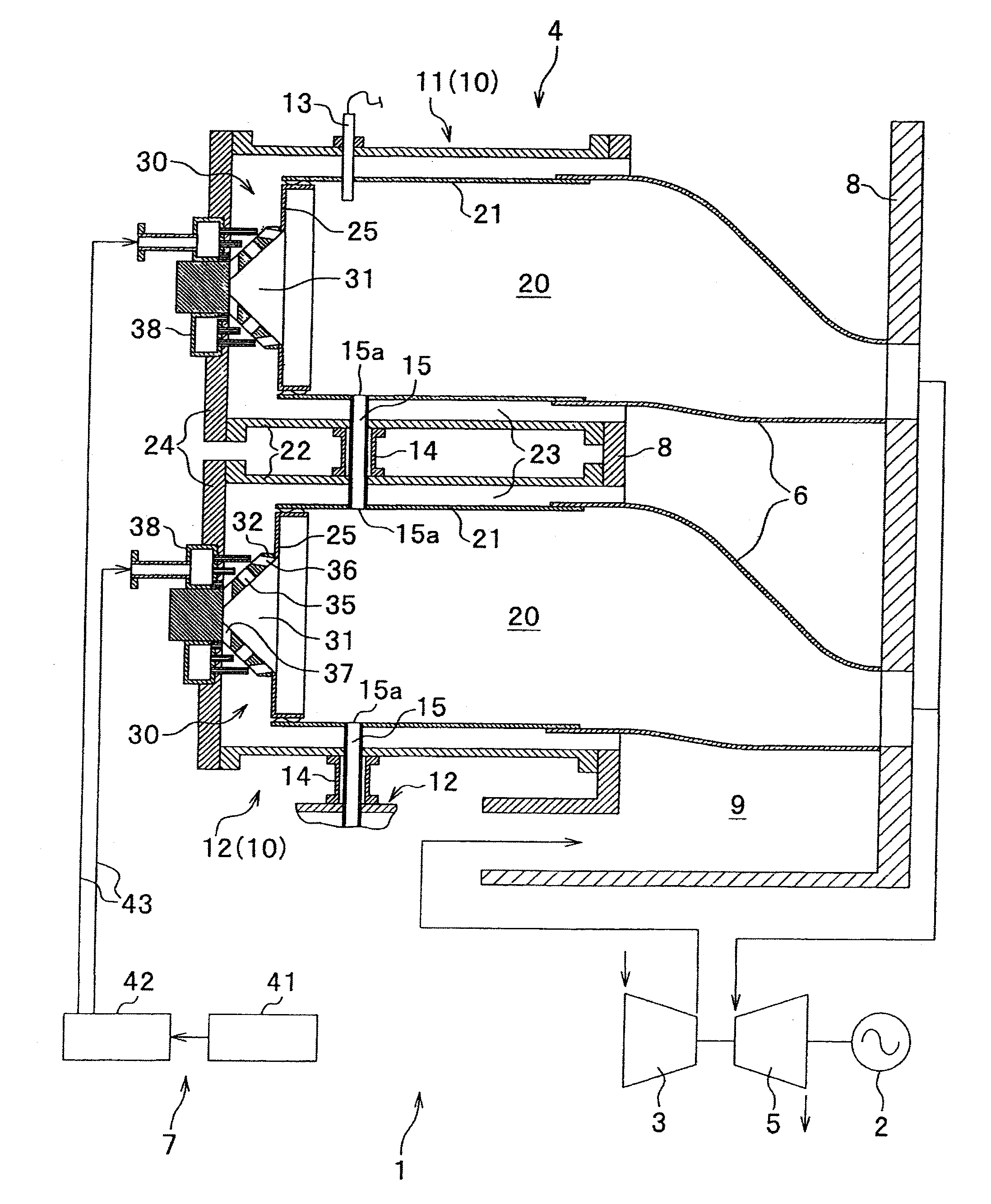
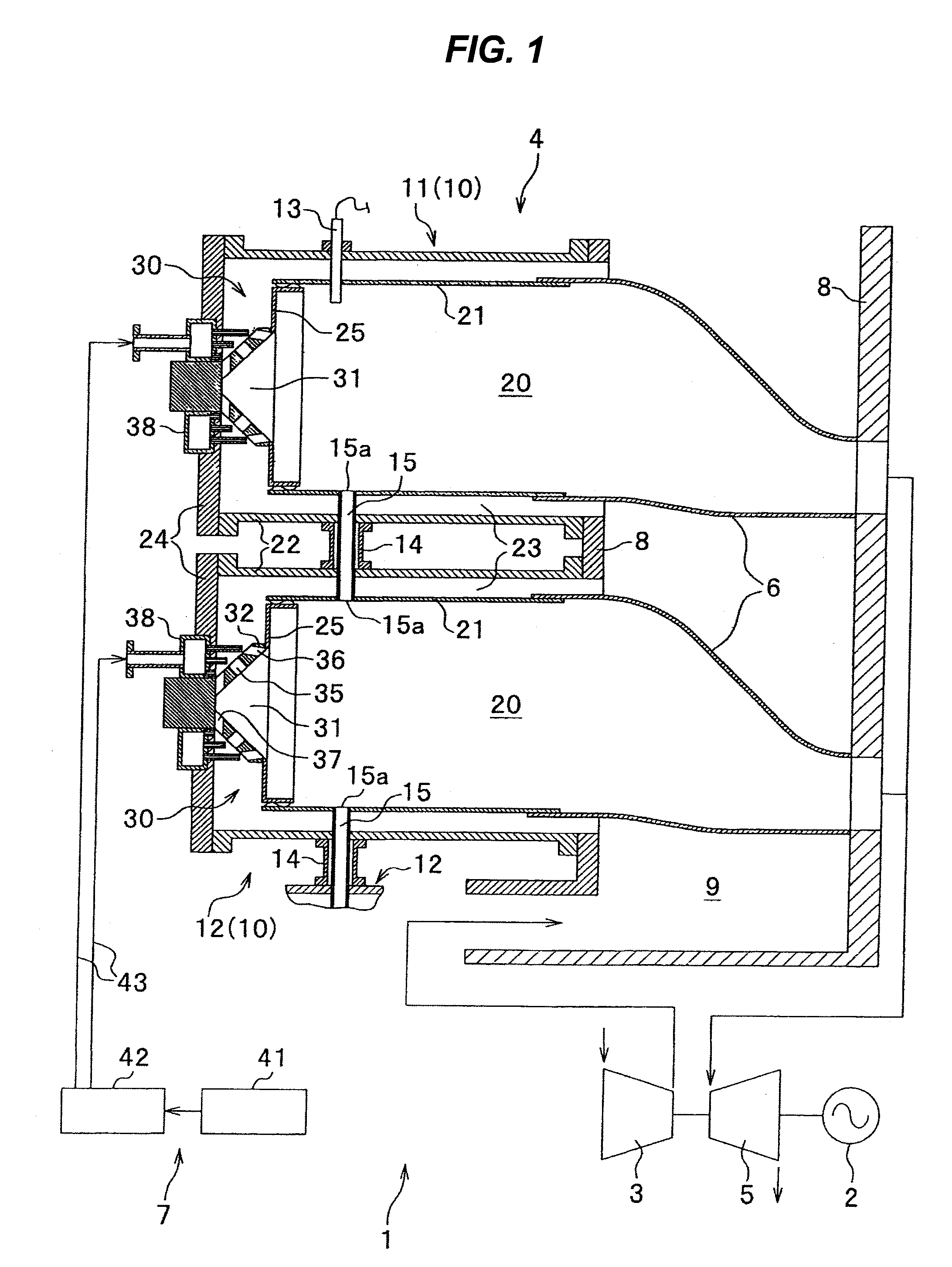
[0038]A gas turbine combustor 4 according to a first embodiment of the invention is described below referring to FIGS. 1 to 5.

[0039]Referring to FIG. 1, a gas turbine plant equipped with a gas turbine 1 is a power-generating gas turbine plant including an electric power generator 2 driven by the gas turbine 1.

[0040]The gas turbine 1 includes: a compressor 3 that compresses air; a gas turbine combustor 4 that creates combustion gases by burning a fuel by means of combustion air which is part of the compressed air obtained in the compressor 3; a turbine 5 that rotates upon being driven by the high-temperature high-pressure combustion gases created by the gas turbine combustor 4; transition pieces 6 that guide the combustion gases from the gas turbine combustor 4 to the turbine 5; a fuel supply system 7 that supplies the fuel, a gaseous fuel such as liquefied natural gas, to the gas turbine combustor 4; and a casing 8 serving to support the gas turbine combustor 4 as well as to form a ...

second embodiment

[0082]A second embodiment of the present invention is described below referring to FIGS. 7 to 9. The second embodiment includes a plurality of main burners 50, 60 disposed at an outer peripheral side of the burner 30, with all other constituent elements of the embodiment being basically the same as in the first embodiment.

[0083]In the second embodiment and in third and fourth embodiments described later herein, description substantially of the same elements as those of the first embodiment is omitted or simplified, with attention being focused primarily upon differences. In addition, the same members as used in the first embodiment, or corresponding members in each of the second to fourth embodiments are each assigned the same reference number or symbol as appropriate. The second to fourth embodiments yield substantially the same operation and effect as those of the first embodiment.

[0084]Furthermore, the mixing chamber walls, mixing chambers 31, and fuel nozzles in the second to fo...

third embodiment

[0107]A third embodiment of the present invention is described below referring to FIGS. 10 to 12.

[0108]Referring to FIGS. 10, 11, burners 70, 80 in combustors 10 equipped in a gas turbine combustor 4 according to the third embodiment include a pilot burner 70 equivalent to the burner 30 in the second embodiment, and a main burner 80.

[0109]The pilot burner 70 includes a mixing chamber wall 72 that forms a conical mixing chamber 71 opening towards a downstream side in an axial direction. The pilot burner 70 also includes a fuel nozzle 79 serving as a central nozzle to supply a fuel. The mixing chamber wall 72 has a mixing chamber wall surface 73 formed into a conical shape, thereby forming the conical mixing chamber 71.

[0110]In the mixing chamber wall surface 72, a plurality of air introduction holes 75, 76 that form a plurality of air introduction passages for introducing combustion air independently or along with fuel into the mixing chamber 71, are arranged in two axial rows, namel...


PUM


Abstract

In a gas turbine combustor, mixing of a fuel and air is accelerated in a mixing chamber of a burner as well as in air introduction passages provided in a wall of the mixing chamber, whereby NOx emissions from premixed combustion are reduced while at the same time, ignition characteristics and flame propagation characteristics improve.The gas turbine combustor includes a plurality of combustors 10, a spark plug 13, and a cross-fire tube 15 that propagates a flame between the combustors 10. Each combustor 10 includes the burner 30 equipped with a fuel nozzle and the mixing chamber wall 32 forming the mixing chamber 31. A plurality of air introduction holes 35, 36 for introducing combustion air, along with the fuel from the fuel nozzle, into the mixing chamber 31, are provided in the mixing chamber wall 32. The combustion air and fuel jetted from the air introduction hole 35 into the mixing chamber 31 are mixed in the form of a mixture “m1”, “m2” and directed towards the spark plug 13 and the cross-fire tube 15.

Description

BACKGROUND OF THE INVENTION[0001]1. Field of the Invention[0002]The present invention relates to a gas turbine combustor including a plurality of combustors for supplying to a turbine, combustion gases resulting from combustion of a fuel-air mixture, a spark plug for igniting the mixture, and cross-fire tubes for propagating flames between the combustors.[0003]2. Description of the Related Art[0004]Among the gas turbine combustors equipped in commonly used conventional gas turbines is traditionally known a type including a plurality of can-type combustors. These combustors are constructed so that each creates high-temperature high-pressure combustion gases by causing reactions between fuel and air in order to rotationally drive the turbine. Such a type of combustor is disclosed in Japanese Patent No. 3940705, for example.[0005]The combustors in the can-type gas turbine combustor are arranged circularly in a circumferential direction of the turbine rotor, and the combustors adjacent ...

Claims


Application Information

Patent Timeline
Patent Type & Authority Applications(United States)
IPC IPC(8): F23R3/28
CPCF23D2207/00F23R3/48F23R3/343F23R3/286
Inventor HIRATA, YOSHITAKAYOSHIDA, SHOHEISEKIGUCHI, TATSUYAHAYASHI, AKINORI
Owner MITSUBISHI HITACHIPOWER SYST LTD
Why Eureka
Try Eureka