
Method and system to detect and measure piping fuel leak

a technology of piping and leakage detection, applied in the direction of electrical control, fire safety, instruments, etc., can solve the problems of increased leakage probability, fire, explosion and to environment contamination, and increased thermal stress level

Inactive Publication Date: 2012-03-01
GENERAL ELECTRIC CO
View PDF6 Cites 15 Cited by
  • Summary
  • Abstract
  • Description
  • Claims
  • Application Information

AI Technical Summary

Benefits of technology

[0051]There are multiple advantages to the described embodiments of the present invention. For example, a fuel leakage in relatively long fuel piping can be detected. Also, a single detector can be utilized to detect the fuel leak and to localize the leak location. In addition, fuel leakage in late lean injection piping can be detected.

Problems solved by technology

Fuel piping leaks could lead to fire, explosion and to environment contaminations.
However, wider temperature ranges usually lead to higher thermal stress levels, and thus increases the probability of leakage.
Unfortunately, the conventional methods fail to address the problem of detecting leakage in relatively long fuel piping.
The conventional methods also fail to address detecting leakage in piping components for gas turbines with late lean injection (LLI) piping.

Method used


Image

  • Method and system to detect and measure piping fuel leak
  • Method and system to detect and measure piping fuel leak
  • Method and system to detect and measure piping fuel leak

Examples


Embodiment Construction

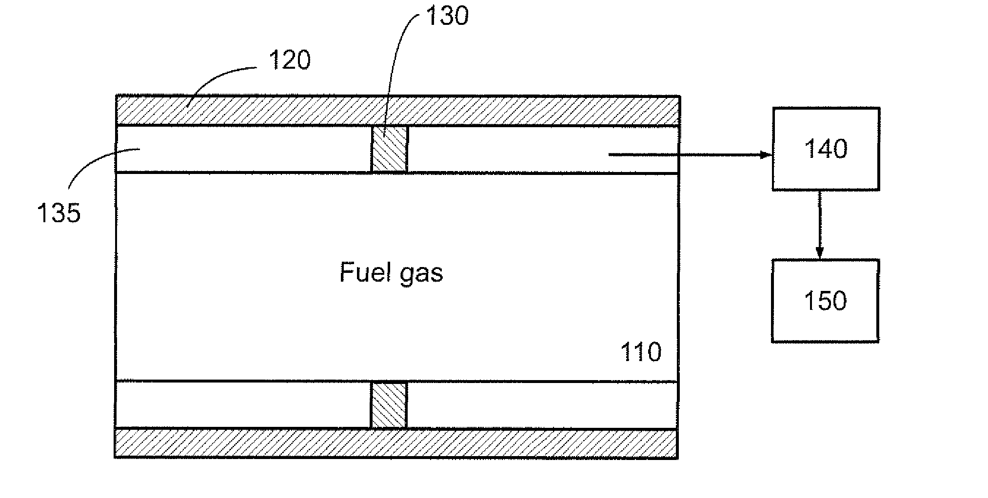
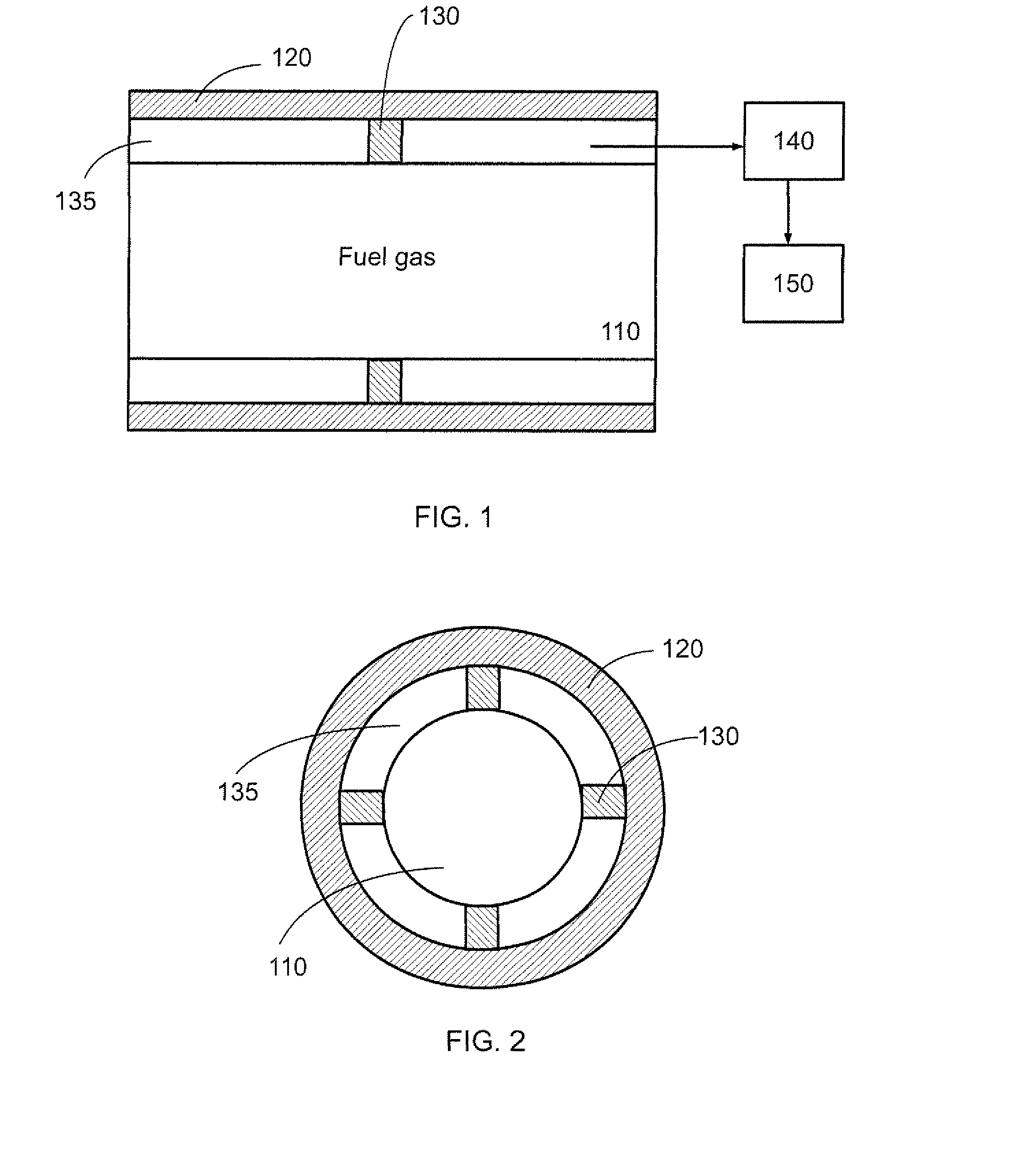
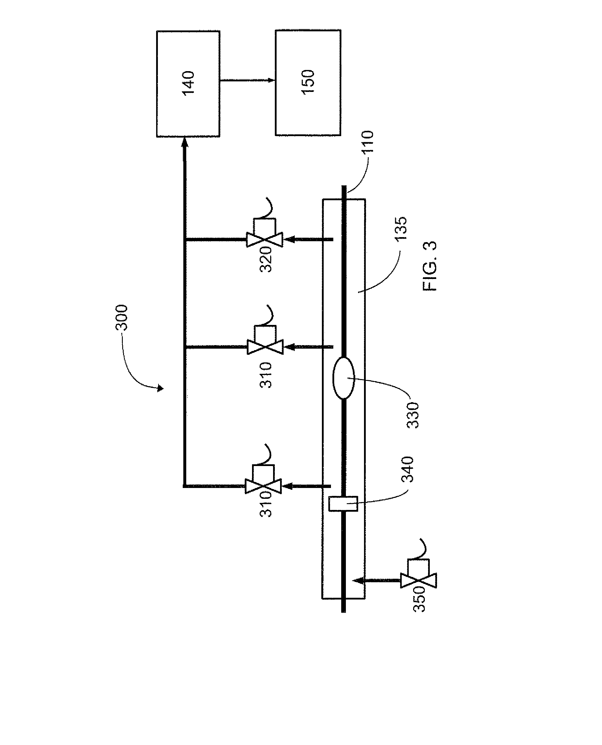
[0018]Novel method and system for measuring and detecting fuel piping leaks are described. The described method and system utilize continuous and / or periodic measurement of the fuel pipes to detect leakage of fuels such as liquid and / or gas hydrocarbons, hydrogen, and oxides of carbon. In general, the fuel piping is enclosed in an air-tight containment structure so that a passage is formed by the fuel piping and the containment structure. Measurements can be conducted, using known hydrocarbon and other combustible gases industrial analyzers, and leak detectors. Pressure drop within the passage can be compensated by controlling of air inlet flow into the passage, coordinated with the analyzer pumping rate. Temperature and motion of the gas sample can be controlled by heating the inlet air. The system can include the controlling valves for the leak source localization.

[0019]FIG. 1 illustrates an embodiment of a fuel pipe set up for detecting a fuel piping leakage according to a non-li...


PUM


Abstract

The described method and system utilize continuous and / or periodic measurement of the fuel pipes to detect leakage of fuel. In general, the piping is enclosed in an air-tight containment cover so that a passage is formed between the piping and containment cover. Measurements can be conducted, using known hydrocarbon and other combustible gases industrial analyzers, and leak detectors. Pressure drop within the passage can be compensated by controlling of air inlet flow into the passage, coordinated with the analyzer pumping rate. Temperature and motion of a gas sample can be controlled by heating the inlet air. The system can includes the controlling valves for the leak source localization. The described method and system can be used to analyze and control fuel leak for late lean injection system for combustor of a turbine.

Description

[0001]One or more aspects of the present invention relate to method and system for continuous and / or periodic measurements of fuel pipes to detect leaks. The method and system are also useful to detect leaks in late lean injection arrangement in combustors of turbines.BACKGROUND OF THE INVENTION[0002]Fuel piping leaks could lead to fire, explosion and to environment contaminations. Also with increasing fuel prices along with diminishing sources of hydrocarbons, fuel piping leakage monitoring has become more important. In addition, there is a growing interest in flexible fuels, i.e. using a wide range of fuels, for gas turbine applications. Flexible fuels require wider temperature ranges to meet delivery and combustion requirements. However, wider temperature ranges usually lead to higher thermal stress levels, and thus increases the probability of leakage.[0003]Some conventional methods to deal with leakage suggest testing for hydrocarbons leakage by building a sealed housing evapor...

Claims


Application Information

Patent Timeline
IPC IPC(8): G01M3/28
CPCF02C7/22F02D2041/225F02M37/0017F23N2031/18F05D2260/80F23K5/007F23K2401/20F02M45/086F23N2231/18F23K2400/20
Inventor KIRZHNER, JOSEPH
Owner GENERAL ELECTRIC CO
Learn More