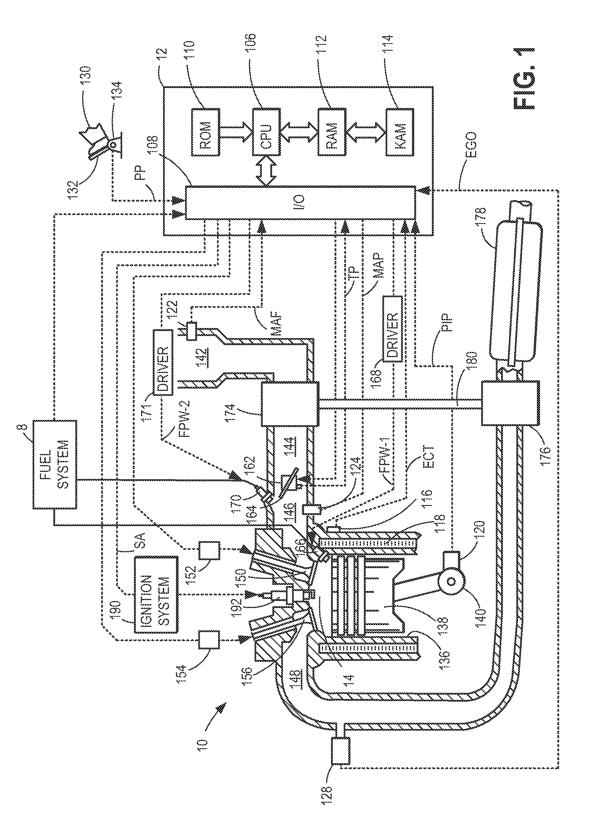
[0001]Various fuel systems may be used to deliver a desired amount of fuel to an engine for
combustion. One type of fuel system includes a port fuel
injector and a direct injector for each engine cylinder. The port injectors may be operated during engine starting to improve fuel
vaporization and reduce engine emissions. The direct injectors may be operated during higher load conditions to improve engine performance. In addition, both port injectors and direct injectors may be operated under some conditions to leverage advantages of both types of
fuel delivery.
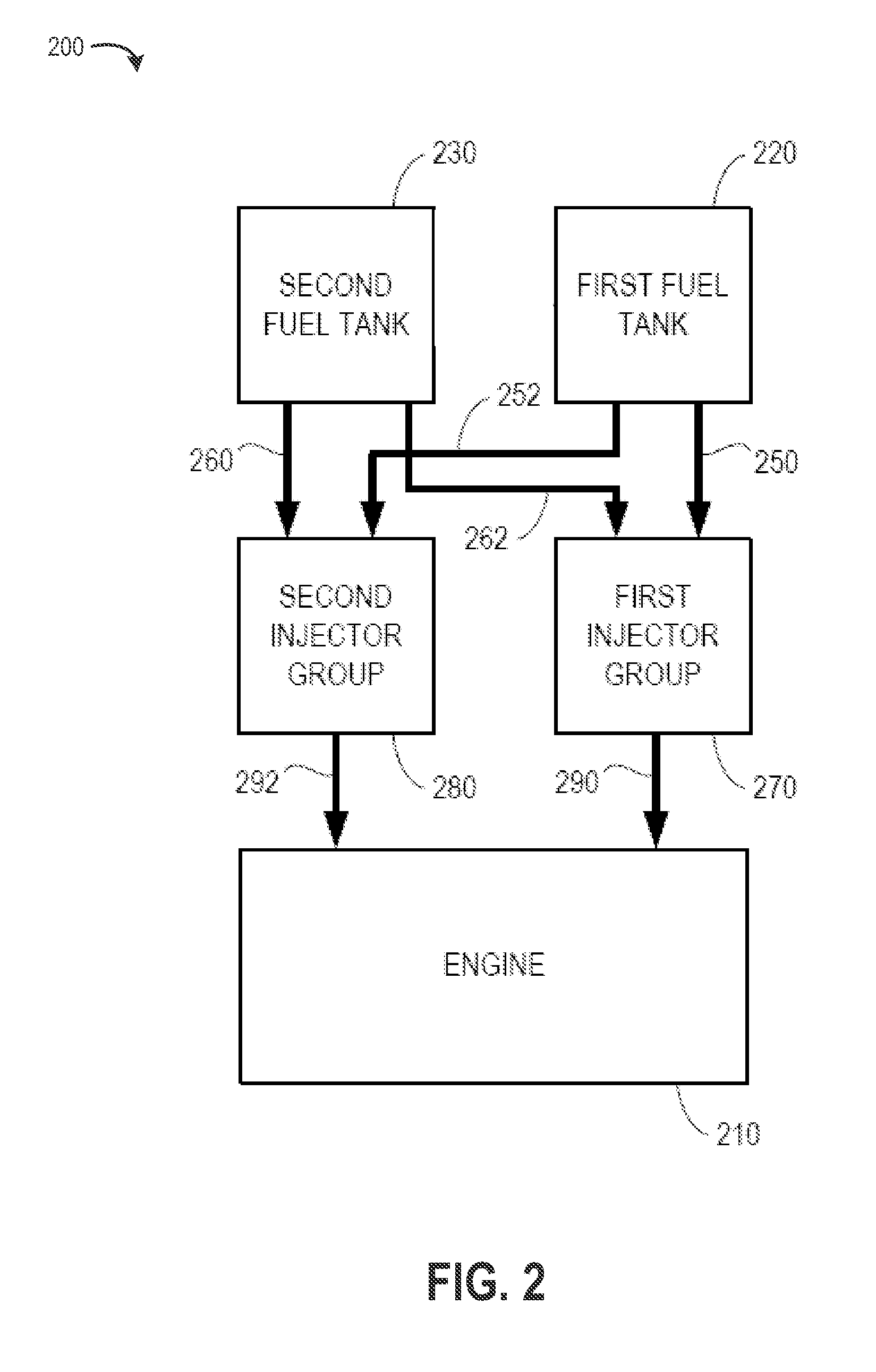
[0004]However, the inventors herein have identified a potential issue with such an approach. As one example, when the fuel tank becomes empty or the fuel level in the fuel tank falls below a threshold, the constant lubrication flow may not be available. Consequently, the high pressure pump may degrade. In particular, in dual fuel systems where the fuel tank coupled to the direct injection system is smaller than the fuel tank coupled to the port injection system, the fuel tank may become empty more often, leading to frequent disabling of the high pressure pump. As such, this may reduce the reliability of the high pressure pump.
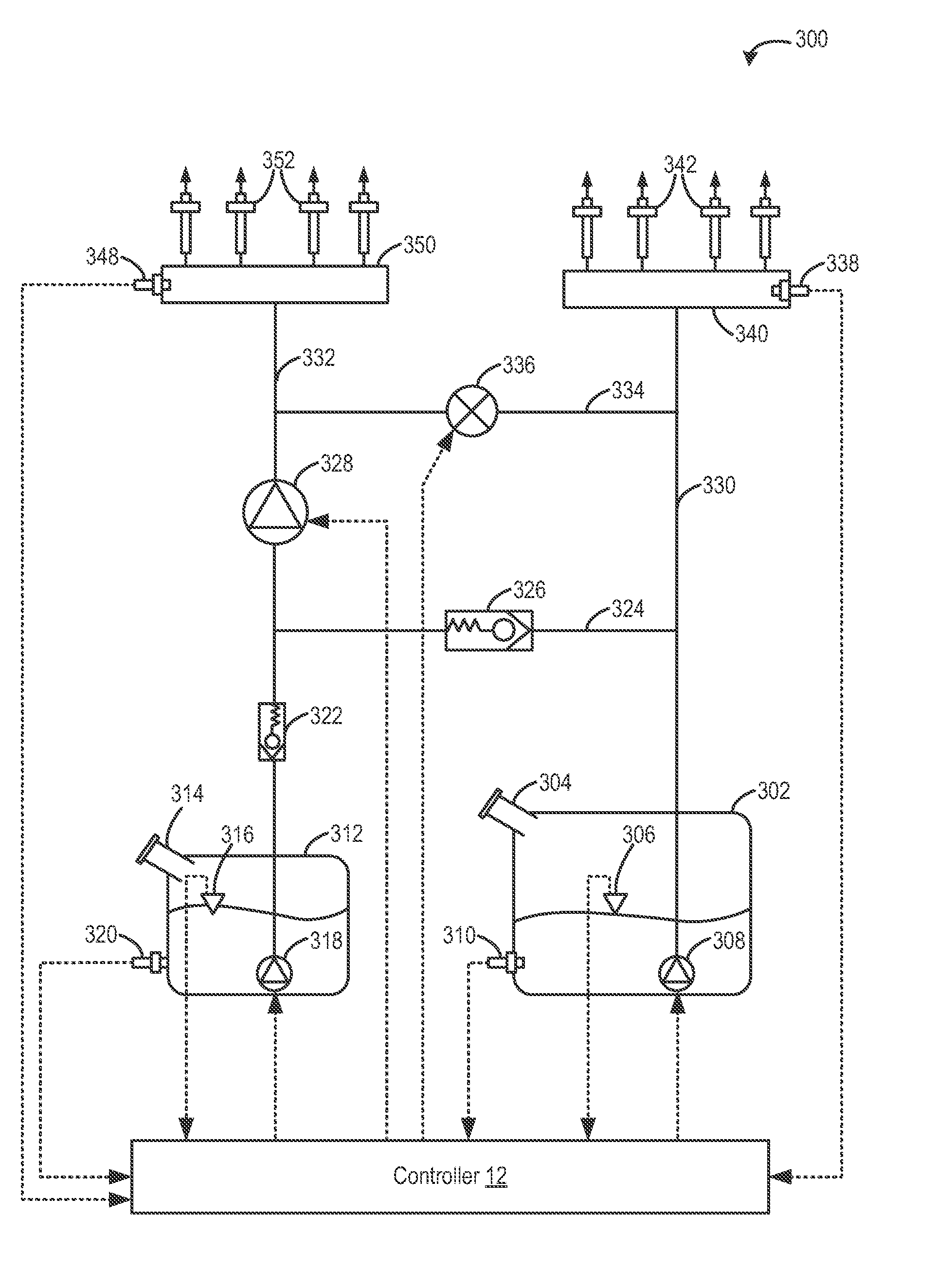
[0010]For example, based on engine operating conditions, as well as an amount of fuel available in each of the first and second fuel tanks, a first amount of the first
fuel type may be port injected into the cylinders. Accordingly, the first low pressure pump may be operated to supply the first fuel to the group of port injectors via the first fuel pump only. In another example, based on operating conditions, a second amount of the second
fuel type may be direct injected into the cylinders. Accordingly, the second low pressure pump may be operated to supply the second fuel to the high pressure pump, and the high pressure pump may be operated to raise the pressure of the received second fuel. The higher pressure fuel may then be supplied from an outlet of the high pressure pump to the second group of direct injectors. As such, when direct injection is enabled, the flow of fuel through the high pressure pump enables sufficient cooling and lubrication of the high pressure pump.
[0011]During selected engine operating conditions, such as when no direct injection of fuel is requested but cooling and / or lubrication of the high pressure pump is required (such as due to the pump temperature exceeding a
threshold temperature and / or a duration of pump operation exceeding a threshold duration), fuel may be port injected into the group of cylinders via the high pressure pump. Specifically, the first low pressure pump may be operated to supply solely the first fuel type from the first fuel tank to the high pressure pump, and the high pressure pump may be operated to supply solely the first fuel type from an outlet of the high pressure pump to a first group of port injectors via the (open)
solenoid valve. An output of the high pressure pump may be coordinated with the output of the first low pressure pump to provide a desired fuel
rail pressure at the first
common rail of the first group of injectors, and to adjust the amount of fluid circulated through the high pressure pump. At the same time, the second low pressure fuel pump and the second group of direct injectors may be deactivated. In this way, by supplying at least some of the first fuel type to the first group of injectors via the high pressure pump, the high pressure pump may be maintained lubricated and cooled even when no direct injection is requested, thereby reducing high pressure pump degradation.
[0012]In another example, when direct injection of the second fuel type is requested, but the level of second fuel in the second fuel tank is below a threshold, the first fuel type may be supplied to the group of direct injectors via the high pressure pump to compensate for the second fuel as well to reduce degradation of the high pressure pump due to fuel insufficiency. Specifically, if the fuel level in the second fuel tank is below the threshold, and high pressure pump cooling and / or lubrication is required, then the first low pressure pump may be operated to supply solely the first fuel type from the first fuel tank to the high pressure pump, and the high pressure pump may be operated to supply solely the first fuel type from the high pressure pump to the group of direct injectors. Herein, the
solenoid valve may remain closed. The controller may determine an amount of first fuel to be direct injected that compensate for the amount of second fuel that was to be direct injected and further to account for high pressure pump cooling and lubrication. Additionally, in case of a sudden surge in cylinder fuel demand, such as during cylinder enrichment, the
solenoid valve may be opened and at least some of the first fuel may also be delivered from the high pressure pump to the first group of port injectors via the solenoid valve so the direct injection of the first fuel is supplemented with the port injection of the first fuel. In this way, by flowing fuel of the first fuel type through the high pressure pump when an insufficient amount of second fuel is available, lubrication and cooling of the high pressure pump is enabled.
[0013]In this way, by circulating at least some fuel from a first fuel tank through the high pressure pump when no direct injection is required, and / or when no fuel from the second tank (coupled to the direct injector) is available, a high pressure pump may be maintained lubricated and cooled, thereby reducing high pressure pump degradation. Furthermore, by reducing the need to disable the high pressure pump due to insufficient availability of second fuel and / or no need for direct injection, high pressure pump reliability may be improved.

