Systems and methods for fluid cooling of electric machines

a technology of fluid cooling and electric machines, applied in the direction of bearing cooling, magnetic circuit rotating parts, magnetic circuit shape/form/construction, etc., can solve the problem of power limitations of electric machines

Inactive Publication Date: 2012-03-01
CLEAN WAVE TECH
View PDF12 Cites 32 Cited by
  • Summary
  • Abstract
  • Description
  • Claims
  • Application Information

AI Technical Summary

Benefits of technology

[0008]A method for cooling an electric machine may be provided in accordance with another aspect of the invention. The method may include providing a rotor fixed to a rotatable shaft, providing a stator stationary in relation to the rotatable rotor and shaft with a gap between the rotor and the stator, and providing a housing surrounding all or part of the machine. The method may also include directing a fluid to flow through one or more passages between the stator and the housing, which may provide the opportunity to directly contact the stator and the rotor with the fluid and transfer heat from the stator and the rotor to the fluid, thereby cooling the stator and the rotor.
[0009]An additional aspect of the invention may be directed to a system for cooling an electric machine. The system may include an electric machine in fluid communication with a pump, and a heat exchanger in fluid communication with the electric machine and the pump. The electric machine may have a fluid-sealed enclosure with at least one inlet and at least one outlet, one or more fluid flow passages in fluid communication with an inlet and an outlet, and a pressure equalization device that may maintain the pressure within the machine within a predetermined range. In some embodiments, the machine may also include a device to determine the level of fluid within the machine. Additionally, in conjunction with the fluid-sealed enclosure, some embodiments may utilize electrically conductive material to comprise the contact seals around the rotating shaft of an electric machine, which may counteract the negative effects of circulating electric currents generated by homopolar flux paths that may exist in electric machines.

Problems solved by technology

Electric machines have power limitations due to the overheating of internal components.

Method used


Image

  • Systems and methods for fluid cooling of electric machines
  • Systems and methods for fluid cooling of electric machines
  • Systems and methods for fluid cooling of electric machines

Examples


Embodiment Construction

[0027]While preferable embodiments of the invention have been shown and described herein, it will be obvious to those skilled in the art that such embodiments are provided by way of example only. Numerous variations, changes, and substitutions will now occur to those skilled in the art without departing from the invention. It should be understood that various alternatives to the embodiments of the invention described herein may be employed in practicing the invention.

I. Fluid Injection System Description

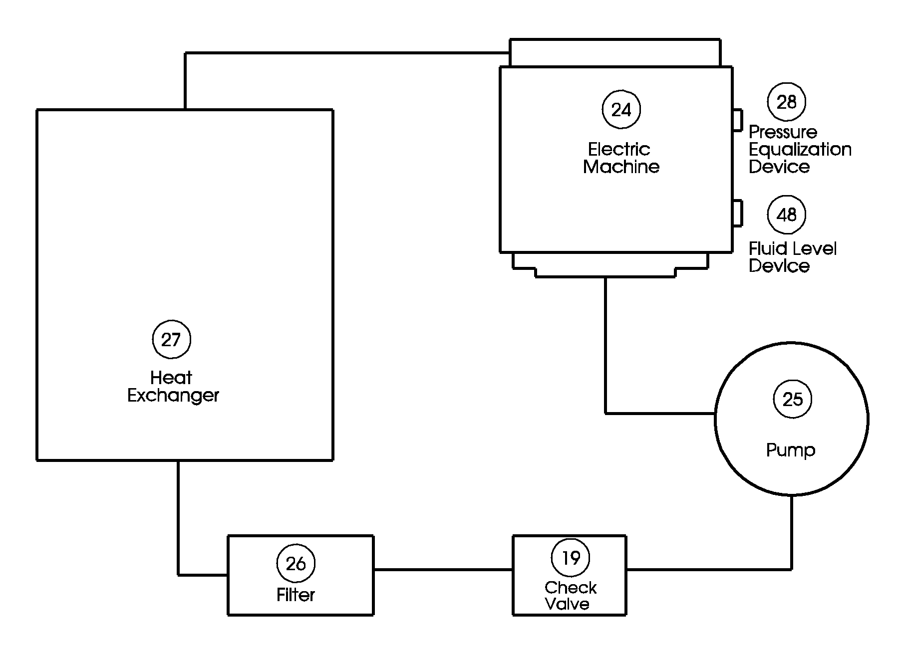
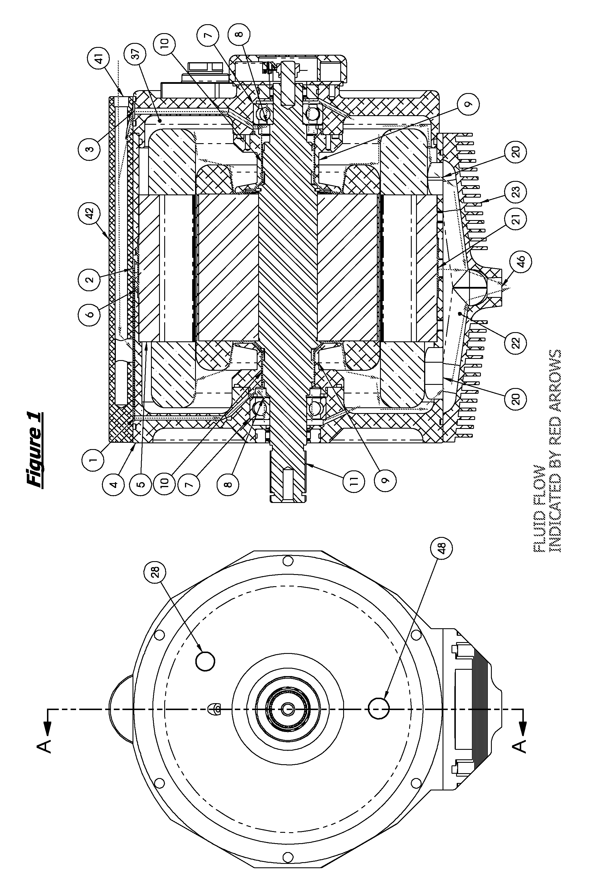
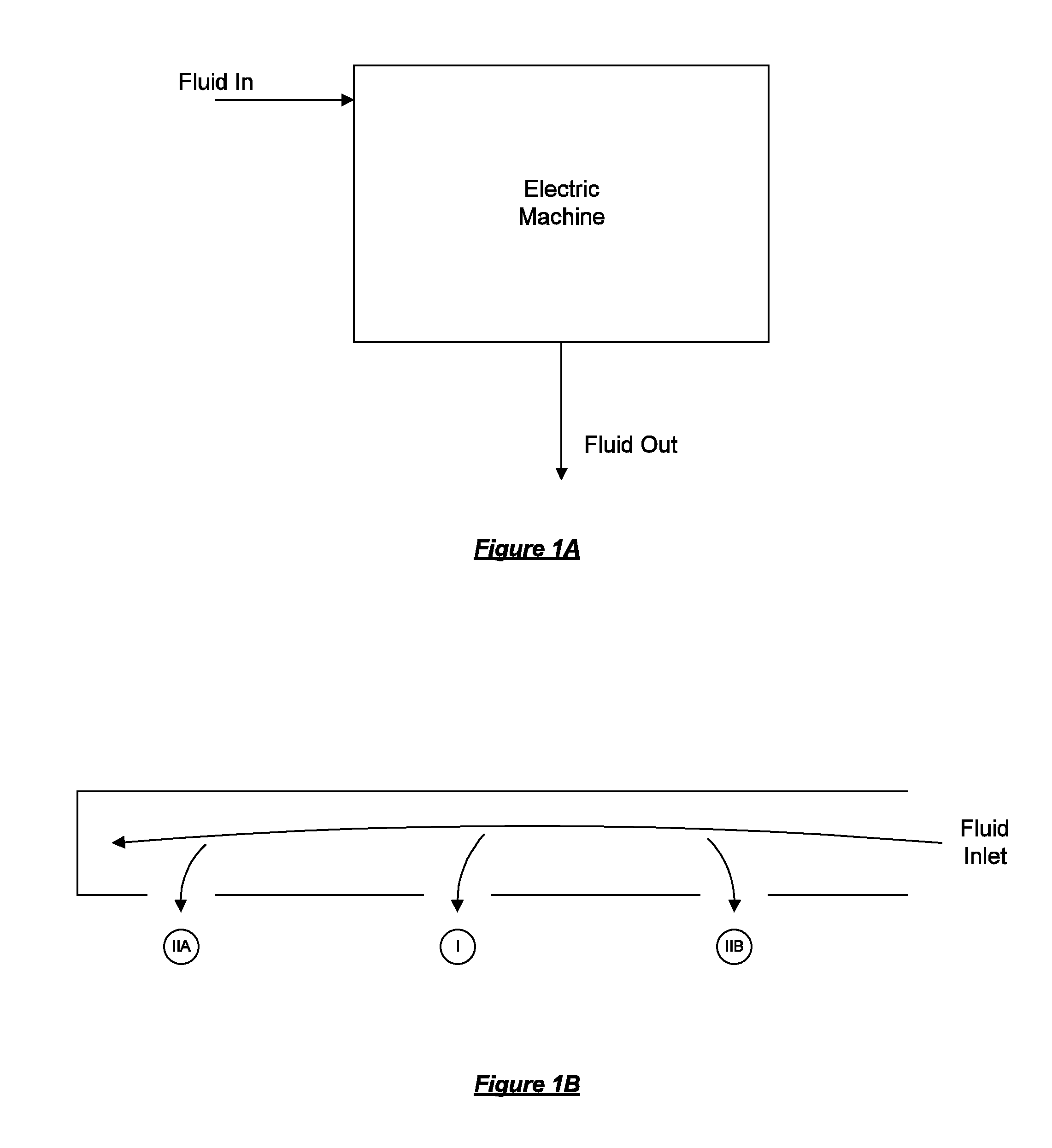
[0028]FIG. 1 shows an electric machine in accordance with an embodiment of the invention. In some embodiments of the invention, the electric machine may be a motor, such as a three-phase AC induction motor. Alternatively, the electric machine may be any sort of motor, generator, or any sort of machine that may require some form of electrical and mechanical connection.

[0029]The electric machine may also be any machine that may be fluid-cooled or that may have any sort of fluid in its ...


PUM


Abstract

The invention provides systems and methods for cooling and lubrication of high power density electric machines with an enhanced fluid injection system. Multiple fluid flow passages may be provided within the electric machine, which may include a stator fluid flow pathway between the stator and the machine housing. The stator fluid flow pathway may comprise one or more passages which may allow a fluid to directly contact the stator and the rotor. A method for cooling the electric machine may include directing a fluid to flow through one or more passages between the stator and the housing, which may provide the opportunity to transfer heat from the stator and the rotor to the fluid, thereby cooling the stator and the rotor.

Description

CROSS-REFERENCE[0001]This application is a continuation-in-part application of Ser. No. 12 / 868,712, filed Aug. 25, 2010, which is incorporated herein by reference in its entirety and to which application we claim priority under 35 USC §120.BACKGROUND OF THE INVENTION[0002]Electric machines have power limitations due to the overheating of internal components. In conventional systems, electric machines are often cooled via exterior cooling. For example, heat sinks may be provided on the external surface of an electric machine to assist with cooling. In some examples, fluid may flow through an outside enclosure of an electric machine or over an external surface of the machine. See, e.g., U.S. Pat. No. 7,550,882; U.S. Pat. No. 5,939,808; U.S. Pat. No. 5,670,838; and U.S. Pat. No. 4,700,092, which are hereby incorporated by reference in their entirety. In some instances, fluid may be provided within an electric machine to assist with cooling, but may be contained within the machine. See,...

Claims


Application Information

Patent Timeline
Patent Type & Authority Applications(United States)
IPC IPC(8): H02K9/19
CPCH02K5/20H02K9/12F16C35/042F16C37/007F16C33/6659H02K5/203H02K9/19F16C2380/26H02K1/20H02K1/32H02K9/193H02K5/15
Inventor GARRIGA, RUDOLPHKUBIC, MIKE
Owner CLEAN WAVE TECH
Why Eureka
Try Eureka