Reflecting sheet and method of fabricating the same

a technology of reflecting sheet and fabricated sheet, which is applied in the field of reflecting sheet, can solve the problems of additional equipment investment, deterioration such as image stain, and achieve the effect of preventing deterioration in display quality

Active Publication Date: 2012-03-01
LG DISPLAY CO LTD
View PDF8 Cites 1 Cited by
  • Summary
  • Abstract
  • Description
  • Claims
  • Application Information

AI Technical Summary

Benefits of technology

[0022]An advantage of the present invention is to provide a reflecting sheet and a method of fabricating the reflecting sheet where adsorption of the reflecting sheet and a light guide plate is prevented due to a reinforcing layer and deterioration in display quality is prevented.
[0023]Another advantage of the present invention is to provide a reflecting sheet and a method of fabricating the reflecting sheet where a base sheet is divided into upper and lower division sheets and each of the upper and lower division sheets is used for the reflecting sheet.
[0024]Additional features and advantages of the invention will be set forth in the description which follows, and in part will be apparent from the description, or may be learned by practice of the invention. These and other advantages of the invention will be realized and attained by the structure particularly pointed out in the written description and claims hereof as well as the appended drawings.
[0025]To achieve these and other advantages and in accordance with the purpose of the present invention, as embodied and broadly described, a method of fabricating a reflecting sheet includes: providing a base sheet including a reflecting layer, an upper surface layer over the reflecting layer and a lower surface layer under the reflecting layer, the reflecting layer including a fine foam; dividing the base sheet into upper and lower division sheets; and forming a reinforcing layer on each of the upper and lower division sheets to constitute the reflecting sheet.
[0026]In another aspect, a reflecting sheet includes: a reflecting layer including a fine foam, the reflecting layer having first and second surfaces opposite to each other; a surface layer on the second surface of the reflecting layer; and a reinforcing layer on at least one of the first surface and the surface layer.
[0027]It is to be understood that both the foregoing general description and the following detailed description are exemplary and explanatory and are intended to provide further explanation of the invention as claimed.

Problems solved by technology

In the LCD device according to the related art, since the weight of the light guide plate is concentrated on the boundary of the concave portion of the bottom frame, the reflecting sheet is partially adsorbed onto the light guide plate and deterioration such as an image stain is caused by the partially pressed contact.
However, since production yield by the method of fabricating the reflecting sheet according to the related art has a limit, an additional investment in equipment is required for increase of production.

Method used


Image

  • Reflecting sheet and method of fabricating the same
  • Reflecting sheet and method of fabricating the same
  • Reflecting sheet and method of fabricating the same

Examples


first embodiment

[0040]FIG. 5 is a perspective view showing a method of fabricating a reflecting sheet according to the present invention.

[0041]In FIG. 5, a base sheet 110 including a synthetic resin where a gas is injected is supplied to a heating apparatus 112. The base sheet 110 is heated at a predetermined temperature in a heating apparatus 112 such as an oven so that a fine foam (not shown) for scattering light can be formed in the base sheet 110. The base sheet 110 outputted from the heating apparatus 112 to a plurality of rolling means 114. The base sheet 110 is cooled and stretched to have a uniform thickness and a uniform flatness while passing through the plurality of rolling means 114. Each of the plurality of rolling means 114 may include upper and lower rollers 128a and 128b. While the base sheet 110 passes through the plurality of rolling means 114, the base sheet 110 is processed to have a uniform thickness and a uniform flatness.

[0042]After the base sheet 110 passes through the plura...

second embodiment

[0055]FIG. 8 is a cross-sectional view showing a reflecting sheet according to the present invention.

[0056]Since a division surface 232 of one of the upper and lower division sheets 122a and 122b (of FIG. 6) is not covered with a surface layer, a fine foam 280 may be damaged by an external impact or the division surface 232 may wrinkle by a heat from a light source.

[0057]In FIG. 8, for the purpose of preventing the above deterioration, a surface layer 260 is disposed to face a light guide plate and the division surface 232 is disposed to face a bottom frame in an LCD device. In addition, a reinforcing layer 240 is formed on the surface layer 260. As a result, the reflecting sheet 250 includes a reflecting layer 252, the surface layer 260 on the reflecting layer 252 and the reinforcing layer 240 on the surface layer 260. The reflecting layer 252 reflects light and includes a fine foam 280. The reinforcing layer 240 includes a bead 240a and a binder 240b for fixing the bead 240a to th...

third embodiment

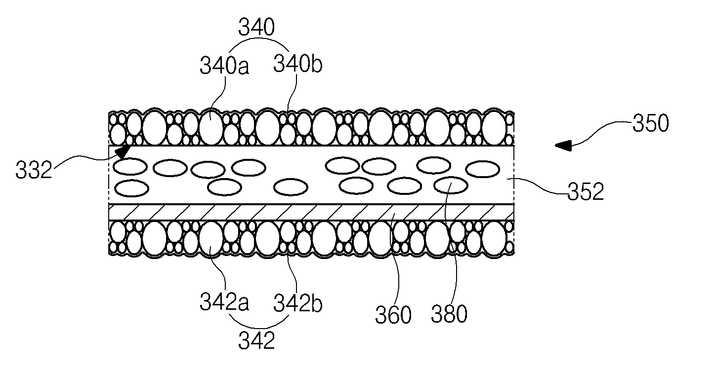
[0061]FIG. 9 is a cross-sectional view showing a reflecting sheet according to the present invention.

[0062]Since a division surface 332 of one of the upper and lower division sheets 122a and 122b (of FIG. 6) is not covered with a surface layer, a fine foam 380 may be damaged by an external impact or the division surface 332 may wrinkle by a heat from a light source when the division surface 332 is disposed to face a light guide plate. In addition, when a surface layer 360 is disposed to face the light guide plate, the surface layer 360 may wrinkle by a heat from a light source and the reflecting sheet 350 may be adsorbed or abraded by the light guide plate.

[0063]In FIG. 9, for the purpose of preventing the above deterioration, upper and lower reinforcing layers 340 and 342 are formed on the division surface 332 and the surface layer 360, respectively. As a result, the reflecting sheet 350 includes a reflecting layer 352, the upper reinforcing layer 340 on the reflecting layer 352, t...


PUM

PropertyMeasurementUnit
thicknessaaaaaaaaaa
thicknessaaaaaaaaaa
thicknessesaaaaaaaaaa

Abstract

A method of fabricating a reflecting sheet includes: providing a base sheet including a reflecting layer, an upper surface layer over the reflecting layer and a lower surface layer under the reflecting layer, the reflecting layer including a fine foam; dividing the base sheet into upper and lower division sheets; and forming a reinforcing layer on each of the upper and lower division sheets to constitute the reflecting sheet.

Description

[0001]This application claims the benefit of Korean Patent Application No. 10-2010-0085161, filed on Aug. 31, 2010, which is hereby incorporated by reference in its entirety.BACKGROUND OF THE INVENTION[0002]1. Field of the Invention[0003]The present invention relates to a reflecting sheet, and more particularly, to a reflecting sheet including a reinforcing layer of a backlight unit and a method of fabricating the reflecting sheet where a base sheet is divided into upper and lower division sheets and a reinforcing layer is formed on at least one of the upper and lower division sheets.[0004]2. Discussion of the Related Art[0005]As information age progresses, demand for display device displaying images has increased in various forms. Recently, various flat panel displays (FPDs) such as a liquid crystal display (LCD), a plasma display panel (PDP) and an organic light emitting diode (OLED) have been utilized. Among the various FPDs, a liquid crystal display (LCD) device has been widely ...

Claims


Application Information

Patent Timeline
Patent Type & Authority Applications(United States)
IPC IPC(8): G02B5/08B05D5/06
CPCG02B1/105G02B5/0808G02B5/0284G02B5/0236G02B1/14
Inventor CHANG, SU-JINMOON, WON-TAEKKIM, SUNG-HUNLEE, SANG-HYUNHAN, SANG-DAE
Owner LG DISPLAY CO LTD
Why Eureka
Try Eureka