Lighting apparatus, headlamp, and mobile body

Active Publication Date: 2012-03-01
SHARP FUKUYAMA LASER CO LTD
View PDF8 Cites 55 Cited by
  • Summary
  • Abstract
  • Description
  • Claims
  • Application Information

AI Technical Summary

Benefits of technology

[0069]In the above-described lighting apparatus according to the fourth aspect, preferably, the laser generator includes a semiconductor laser device. With this design, it is possible to easily make the lighting apparatus compact.
[0070]According to a fifth aspect of the invention, a headlamp is provided with a lighting apparatus as described above. With this design, it is possi

Problems solved by technology

Inconveniently, however, when the light source apparatus of JP-A-2003-295319 mentioned above is applied to the headlamps of an automobile, changing the illuminating direction of the light source apparatus requires changing the orientation of the reflector (light projecting member).
This necessitates a member fo

Method used


Image

  • Lighting apparatus, headlamp, and mobile body
  • Lighting apparatus, headlamp, and mobile body
  • Lighting apparatus, headlamp, and mobile body

Examples


embodiment 1

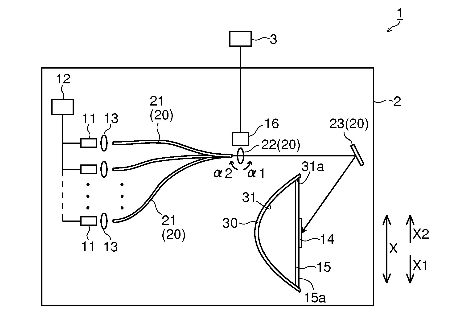
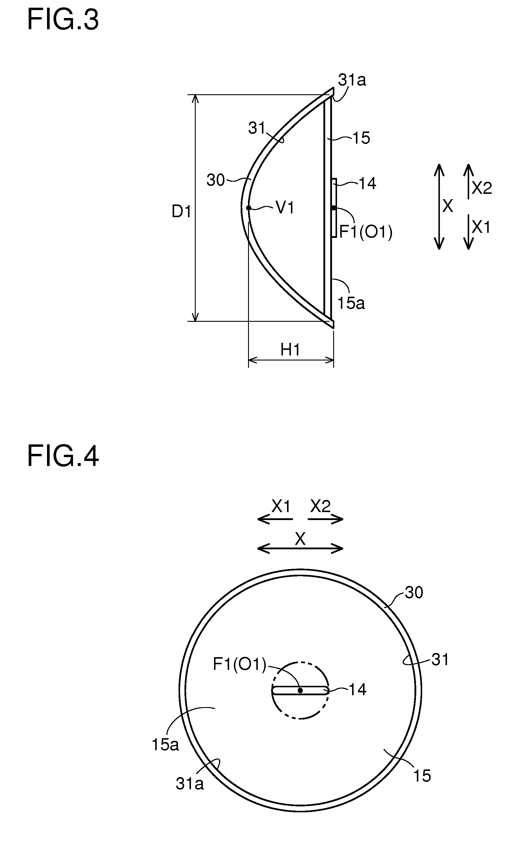
[0166]First, with reference to FIGS. 1 to 5, the design of an automobile 1 provided with a headlamp 2 according to a first embodiment (Embodiment 1) of the invention will be described.

[0167]As shown in FIG. 1, the automobile 1 according to Embodiment 1 is provided with a headlamp 2 which illuminates forward in the traveling direction during traveling at night, for instance, and a steering angle detector 3 which detects the steering angle of the automobile 1 from a steering wheel or wheels (unillustrated). The automobile 1 is an example of a “mobile body” according to the invention, and the headlamp 2 is an example of a “lighting apparatus” according to the invention.

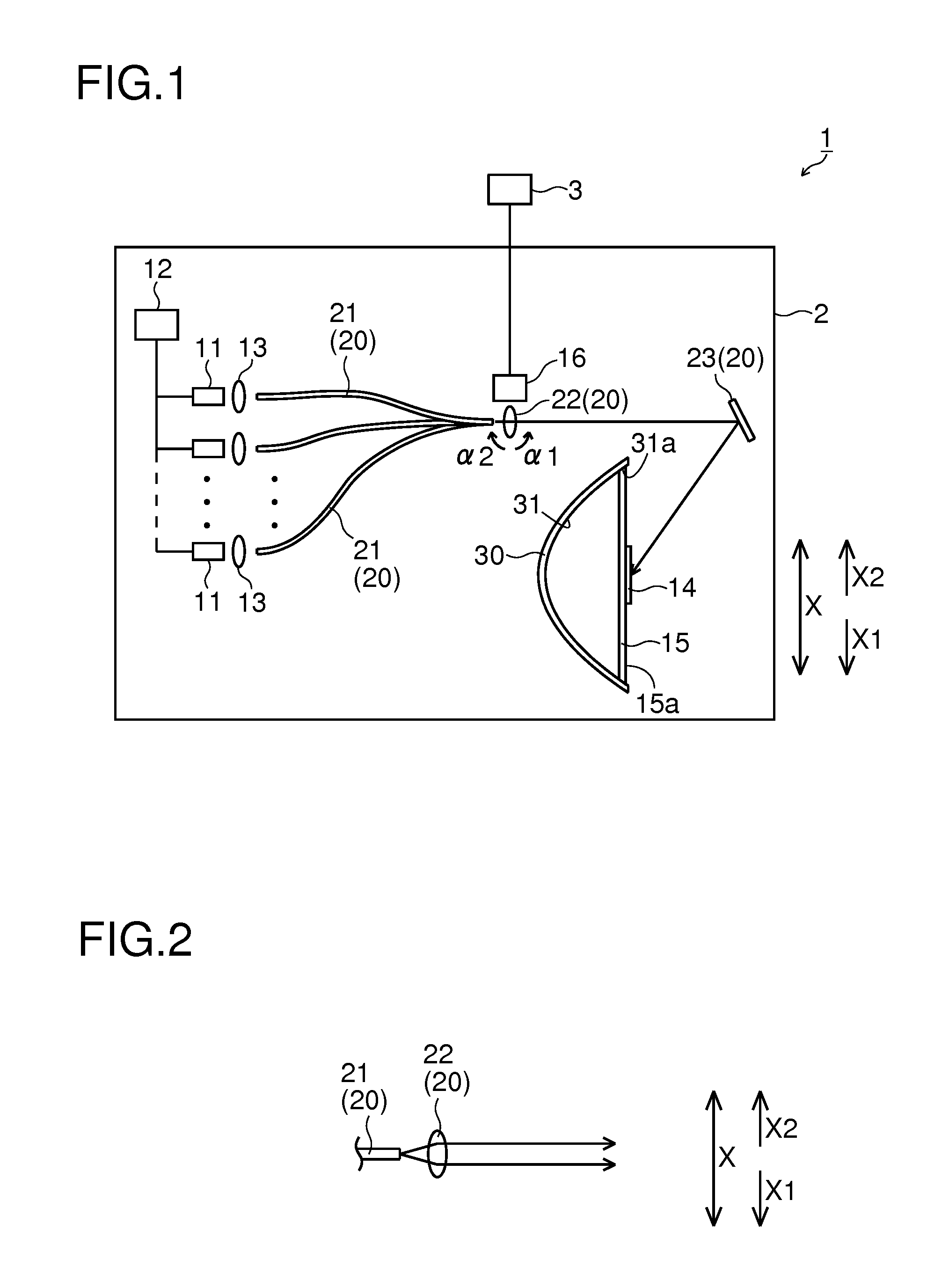
[0168]The headlamp 2 includes: a plurality of (for example, ten) semiconductor laser devices 11 which function as a laser light source; an output adjuster 12 which adjusts the output of the semiconductor laser devices 11; light guide members 20 which are provided on the laser light exit side of the semiconductor laser de...

embodiment 2

[0212]As a second embodiment (Embodiment 2) of the invention, with reference to FIGS. 13 to 21, a description will be given of a case where, as distinct from in Embodiment 1 described previously, the focal point F101 of the reflective surface 131 is located near the vertex V101.

[0213]First, with reference to FIGS. 13 to 16, the design of an automobile 101 provided with a headlamp 102 according to Embodiment 2 will be described.

[0214]As shown in FIG. 13, the automobile 101 according to Embodiment 2 is provided with a headlamp 102 and a steering angle detector 3 which detects the steering angle of the automobile 101. The automobile 101 is an example of a “mobile body” according to the invention, and the headlamp 102 is an example of a “lighting apparatus” according to the invention.

[0215]The headlamp 102 includes: a plurality of (for example, ten) semiconductor laser devices 111; an output adjuster 12; light guide members 20; condenser lenses 13; a fluorescent member 114; a holding me...

embodiment 3

[0242]As a third embodiment (Embodiment 3) of the invention, with reference to FIG. 22, a description will be given of a case where, as distinct from in Embodiment 1 described previously, laser light is applied to the fluorescent member 214 from behind.

[0243]In the headlamp according to Embodiment 3, as shown in FIG. 22, in a portion of the reflector 230 including the vertex of the reflective surface 231, an opening 230a is formed. The reflector 230 is an example of a “light projecting member” and a “first reflector” according to the invention.

[0244]The fluorescent member 214 here is, like the fluorescent member 114 in Embodiment 2 described previously, formed by dispersing, in UV-curing resin, about 30% by weight of mixed powder of phosphor particles of Ce3+-activated α-SiAlON and phosphor particles of CaAlSiN3:Eu2+, then applying the UV-curing resin on the holding member 15 in a layer with a thickness of about 0.2 mm, and then curing the UV-curing resin. The fluorescent member 214...


PUM


Abstract

A lighting apparatus is provided that, while suppressing an increase in size, can change the illuminating direction. The lighting apparatus has: a laser generator which emits laser light; a light emitting member which is irradiated with the laser light emitted from the laser generator to emit light; an irradiated position changer which moves and thereafter stops an irradiated position at which the light emitting member is irradiated with the laser light; and a light projecting member which projects the light emitted from the light emitting member.

Description

[0001]This nonprovisional application claims priority under 35 U.S.C. §119(a) on Patent Applications Nos. 2010-193357 and 2010-193358 filed in Japan on Aug. 31, 2010, and Patent Applications Nos. 2011-152517 and 2011-152518 filed in Japan on Jul. 11, 2011, the entire contents of all of which are hereby incorporated by reference.BACKGROUND OF THE INVENTION[0002]1. Field of the Invention[0003]The present invention relates to lighting (illuminating) apparatus, headlamps, and mobile bodies, and more particularly to those employing a laser generator which emits laser light.[0004]2. Description of Related Art[0005]There are conventionally known lighting apparatus employing a laser generator which emits laser light. Such lighting apparatus are disclosed in, for example, JP-A-2003-295319.[0006]JP-A-2003-295319 mentioned above discloses a light source apparatus (lighting apparatus) provided with an ultraviolet LD device (laser generator) which functions as a laser light source, a phosphor (f...

Claims


Application Information

Patent Timeline
IPC IPC(8): B60Q1/00F21V13/00
CPCF21S48/1145F21S48/1241F21S48/1323F21S48/1757F21V13/00F21Y2101/025F21S48/10F21S48/1705F21V13/02F21V29/004F21V13/04F21Y2115/30F21Y2115/10F21S41/24F21S41/321F21S41/675F21S41/16F21S41/176F21S41/60
Inventor TAKAHASHI, KOJI
Owner SHARP FUKUYAMA LASER CO LTD
Why Eureka
Try Eureka