Multiple Access Method and Apparatus

a multi-burst receiver and access method technology, applied in the field of multi-burst receivers, can solve the problems of system capacity increase and transmission uncoordination, and achieve the effects of improving performance, and significantly complex multi-burst receivers

Inactive Publication Date: 2012-03-01
INMARSAT GLOBAL
View PDF12 Cites 9 Cited by
  • Summary
  • Abstract
  • Description
  • Claims
  • Application Information

AI Technical Summary

Benefits of technology

[0015]The complexity of a multi-burst receiver is significantly higher than that of a single channel receiver. Complexity is transferred into the receiver incorporating new functions which can extract information from a composite signal. The complexity of a multi-burst receiver is higher than conventional single-burst receivers. In general, as the receiver becomes more complex, its performance improves. However, there is a practical limit on how complex the receiver can be.
[0016]Embodiments of the invention may provide a minimum complexity architecture that retains most of the performance benefits mentioned above. The architecture may bridge the gap between single burst and multi-burst receivers. Furthermore, this architecture appears to perform very well with a realistic operational scenario and with the potential of

Problems solved by technology

The system capacity increases as the coding rate de

Method used


Image

  • Multiple Access Method and Apparatus
  • Multiple Access Method and Apparatus
  • Multiple Access Method and Apparatus

Examples


Embodiment Construction

[0034]Joint Multiple Access Scheme

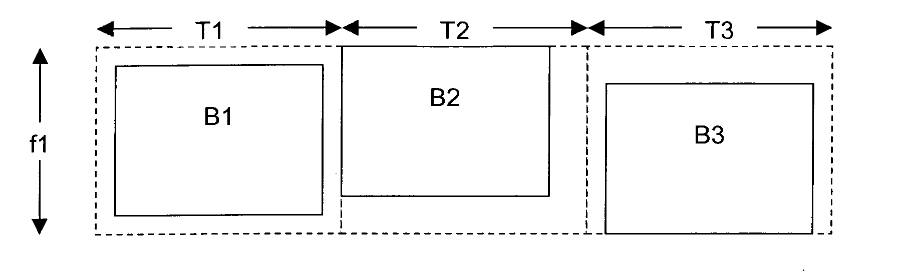
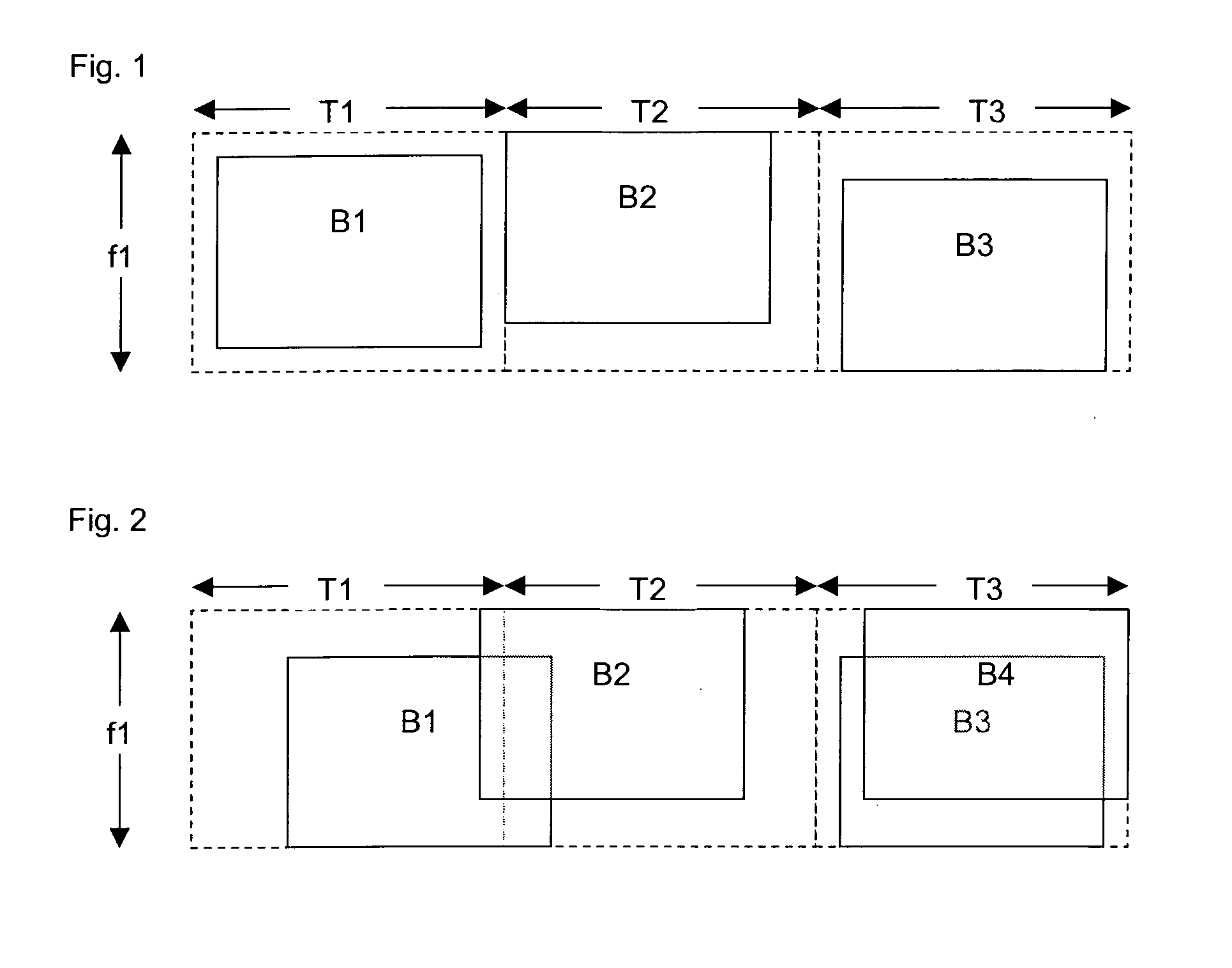
[0035]In a TDMA system in an embodiment of the invention, as shown in FIG. 2 and in contrast to FIG. 1, bursts B1 . . . B4 are nominally aligned with respective time slots T1 . . . T4, but are allowed to overlap between adjacent time slots, as shown by bursts B1 and B2 over time slots T1 and T2 and / or may occupy substantially the same time slot, as shown by bursts B3 and B4 substantially completing overlapping in timeslot T3. In other words, bursts are not mutually separated by time and / or frequency, but are allowed joint access to time and / or frequency channels. Nevertheless, the system may control joint access statistically, by controlling how transmitters select time and frequency channels for themselves, so that the receiver is likely to be able to decode each burst, using multi-burst decoding.

[0036]This scheme can significantly increase system capacity by increasing the energy density in the channel, while simultaneously reducing service latenc...


PUM


Abstract

A wireless multiple access method allows multiple transmitters to access the same channels so that substantial interference occurs. The transmitters use low rate turbo coding and the receiver uses multi-user detection to separate and decode the transmissions. Different propagation and/or transmission characteristics between the transmitters help to distinguish the transmissions at the receiver. The transmitters may add random variation to their transmission timing, power and/or frequency to assist with decoding.

Description

FIELD OF THE INVENTION[0001]The present invention relates to a novel multiple access method, and to apparatus for implementing the method.BACKGROUND OF THE INVENTION[0002]The operational cost of low data rate mobile geostationary (GEO) satellite systems is relatively expensive when compared to fixed or transportable counterparts due to their low gain antenna, limited transmit power and extensive fading margin. For such systems more satellite resources, such as bandwidth and power, should be made available to accommodate poor propagation conditions which usually become worse as the user terminals operate at the edge of coverage, viewing the satellite at lower elevation angle (e.g. as low as 5°). One approach is to limit the service area so that only high elevation satellite links are allowed (e.g. higher than 20°) ensuring good propagation conditions, but this clearly does not satisfy the requirements for provision of services at high latitudes such as Northern European countries. On...

Claims


Application Information

Patent Timeline
IPC IPC(8): H04B7/00
CPCH04L1/0045H04B7/02H04L1/0066
Inventor FEBVRE, PAULFINES, PANAGIOTISCHRISTOFYLAKI, EKATCRINA
Owner INMARSAT GLOBAL
Why Eureka
Try Eureka