Medical image alignment apparatus, method, and program

Inactive Publication Date: 2012-03-01
FUJIFILM CORP
View PDF4 Cites 27 Cited by
  • Summary
  • Abstract
  • Description
  • Claims
  • Application Information

AI Technical Summary

Benefits of technology

[0067]In the case where the vertebra alignment unit aligns the third characteristic amount calculated from the three-dimensional image with the third characteristic amount calculated from three-dimensional comparison image using an SSD method, a position on the central axis of the three-dimensional comparison image where the third characteristic amount of the three-dimensional image best matches with the third characteristic amount of the three-dimensional comparison image over the entire evaluation range may be accurately calculated as the position on the central axis of the three-dimensional comparison image corresponding to a given position on the central axis of the three-dimensional image.
[0068]In the case where the vertebra alignment unit aligns the third characteristic amount calculated from the three-dimensional image with the third characteristic amount calculated from three-dimensional comparison image with respect to each point on the central axis using a dynamic programming method (DP method), each position on the central axis of the three-dimensional comparison image where the third characteristic amount of the three-dimensional image best matches with the third characteristic amount of the three-dimensional comparison image may be calculated with respect to each position on the central axis of the three-dimensional image, each position on the central axis of the three-dimensional comparison image may be calculated accurately with respect to each position on the central axis of the t

Problems solved by technology

But, it is difficult to extract axial images at precisely corresponding chest positions.
For example, the aforementioned method may not respond to the demand for performing comparative image reading with respect to a cross-sectio

Method used


Image

  • Medical image alignment apparatus, method, and program
  • Medical image alignment apparatus, method, and program
  • Medical image alignment apparatus, method, and program

Examples


first embodiment

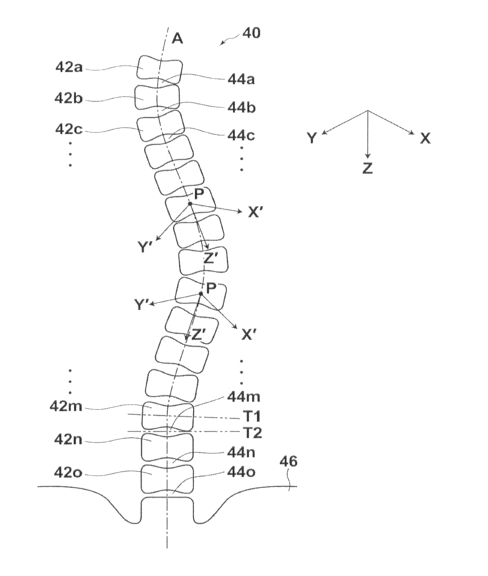
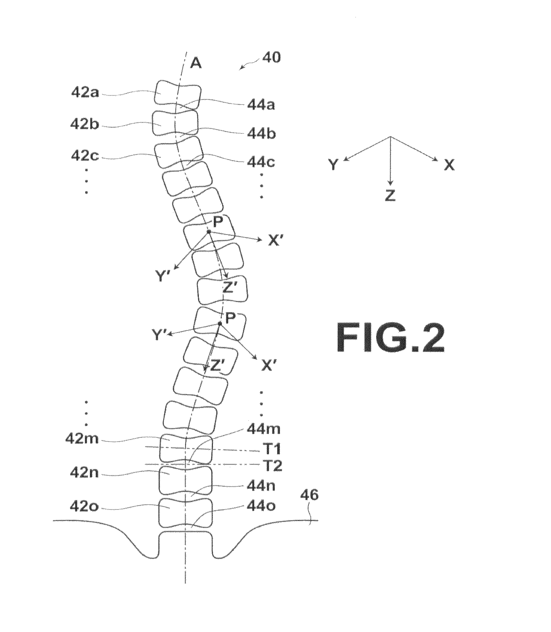
[0169]FIG. 8 illustrates corresponding positions on each vertebra center line of the three-dimensional image and the three-dimensional comparison image in the As illustrated in FIG. 8, n positions P1i (0≦i≦n, i and n are positive integers) are sequentially set at an equal interval on the central axis Z1′ of the three-dimensional image V1 within the range 0≦z′≦Z′ from the cervical vertebrae toward caudal vertebrae in the present embodiment. Then, with respect to each position P1i (0≦i1′ of the three-dimensional image V1, a position P2i (0, 0, zi′+s) on the central axis Z2′ of the three-dimensional image V2 corresponding to position P1i (0, 0, zi′) is obtained.

[0170]Then, alignment unit 17 converts corresponding positions on the central axis Z′ of the three-dimensional image V1 and the three-dimensional comparison image V2 to a position in an XYX coordinate system (S08). Vertebra position estimation unit 36 converts the position of each vertebra 42 on Z′ axis estimated in step S08 to...

second embodiment

[0184]In the second embodiment, a squared sum of the difference between a third characteristic amount at each position z′ on a central axis Z1 of a three-dimensional image V1 and a third characteristic amount at a position z′+Sz′, which is the position shifted by a shift amount of SZ′, from the position z′ on a central axis Z2 of a three-dimensional comparison image V2 is minimized for each position z′ on a central axis Z1 of a three-dimensional image V1 to obtain a shift amount SZ′, at each minimized position by a dynamic programming method, instead of the SSD method. More specifically, a shift amount that minimizes an evaluation function of formula (5) given below.

minargsz′∑z′=0Z′(f32(z′+sz′)-f31(z′))2(5)

[0185]According to this method, with respect to each position z′ within the range of 0≦z′≦Z′, a shift amount SZ′, that best matches the third characteristic amount of the three-dimensional image V1 with the third characteristic amount of the three-dimensional comparison image V2 m...

third embodiment

[0189]As the third embodiment, display control unit 18 displays tomographic images (second tomographic images) orthogonal to the central axes at each position along the central axes. FIG. 10 schematically illustrates a sagittal image of a three-dimensional image V1 of a subject having a totally curve deformed spine and a corresponding sagittal image of a three-dimensional comparison image V2. It is assumed that the three-dimensional image V1 was obtained by CT imaging a subject several days before comparative image reading is performed while the three-dimensional comparison image V2 was obtained by CT imaging the same subject several months before the comparative image reading is performed.

[0190]In the third embodiment, processing of S01 to S08 shown in FIG. 3A is identical to that in the first embodiment. That is, three-dimensional images V1 and V2 are obtained, first tomographic images along a body axis direction are obtained with respect to each of the three-dimensional images V1...


PUM


Abstract

Generating, with respect to each of the three-dimensional image and the three-dimensional comparison image, a plurality of tomographic images orthogonal to a central axis of each vertebra of the subject along the central axis, calculating a first characteristic amount representing a profile in a direction orthogonal to the central axis at each point on the central axis based on the tomographic images, calculating a second characteristic amount representing a profile in a direction of the central axis at each point on the central axis based on the tomographic images, calculating a third characteristic amount representing regularity of disposition of each vertebra at each point on the central axis based on the calculated first and second characteristic amounts, and aligning positions of the third characteristic amount calculated from the three-dimensional image and the third characteristic amount calculated from the three-dimensional comparison image along the central axis.

Description

BACKGROUND OF THE INVENTION[0001]1. Field of the Invention[0002]The present invention relates to a medical image alignment apparatus, method, and program for determining positional correspondence relationship between a plurality of three-dimensional images which include vertebrae. The invention also relates to a cross-sectional spine image display apparatus, method, and program, and more particularly to a cross-sectional spine image display apparatus, method, and program for generating a cross-sectional image of a vertebra portion based on three-dimensional image data and displaying the generated image.[0003]2. Description of the Related Art[0004]When performing comparative image reading of a plurality of three-dimensional images formed of a plurality of cross-sectional images sliced in a direction orthogonal to a body axis direction, there is a demand for displaying corresponding cross-sectional images of each three-dimensional image side by side by performing site recognition and ...

Claims


Application Information

Patent Timeline
IPC IPC(8): A61B6/03
CPCA61B6/03A61B6/463A61B6/505A61B6/5217G06T2207/30012G06T7/0012G06T7/0028G06T2207/10072A61B6/5223G06T7/33G16H50/30
Inventor WANG, CAIHUANAKAMURA, KEIGOIHARA, SATOSHI
Owner FUJIFILM CORP
Why Eureka
Try Eureka