Flowmeter for detecting a property of a fluid medium

a flowmeter and fluid medium technology, applied in the field of technology and natural sciences, can solve the problems of substantial dynamic errors of devices operating according to the bernoulli principle or other differential pressure measuring principles, and high inaccuracy of individual measuring principles

Inactive Publication Date: 2012-03-08
ROBERT BOSCH GMBH
View PDF15 Cites 30 Cited by
  • Summary
  • Abstract
  • Description
  • Claims
  • Application Information

AI Technical Summary

Benefits of technology

[0007]In accordance with the present invention, the dynamic errors described here for devices operating according to the differential pressure principle may be prevented or at least reduced by using at least one additional measuring principle, which is independent of the properties of the medium. To detect a large throughput range, therefore at least two measuring principles, an ultrasonic measuring principle and a differential pressure measuring principle are combined. The ultrasonic measuring principle may be used in particular to detect a low throughput range and thus in particular small flow rates. On the other hand, the differential pressure principle may be used for a high throughput range in particular and consequently for high flow quantities. It is therefore possible to combine two measuring principles which are relatively insensitive with respect to contamination with foreign bodies, for example, dust, particles, dirty water and oil, so that measuring ranges which are otherwise achievable only with thermal flowmeters are achieved.
[0016]A preferred specific embodiment is a flowmeter in which the ultrasonic sensor and the differential pressure sensor are positioned essentially in the same position in or on the flow tube, based on the main direction of flow. Differences in position of the ultrasonic sensor, i.e., the differential pressure sensor, are based on the arithmetic mean of the position of the particular sensors in the main direction of flow. “Essentially in the same position” preferably means that the differential pressure sensor is no more than 20 mm away from the ultrasonic sensor in the main direction of flow. For example, the arithmetic mean of two ultrasonic transducers may denote the position of the ultrasonic sensor. With respect to the differential pressure sensor, for example, the arithmetic mean of the positions of at least two pressure sensors, of at two pressure measuring sites and / or an arithmetic mean of the positions of one or more absolute pressure gauges and one or more differential pressure gauges may indicate the position of the differential pressure sensor. The differential pressure sensor and the at least one ultrasonic sensor should be separated from one another by no more than 2 ms with respect to the minimal transit time of the fluid medium in the flow tube to avoid an excessive variance in the measured values of the two sensors. The at least one ultrasonic sensor and the at least one differential pressure sensor may also therefore overlap completely or partially in the direction of flow. For example, one ultrasonic transducer of the ultrasonic sensor may be situated upstream from the differential pressure sensor, while a second ultrasonic transducer of the ultrasonic sensor may be situated downstream from the differential pressure sensor. This achieves the result that the two measuring signals originate from the same location in the flow tube and thus no inaccuracies may occur between the two measuring signals, which could arise because of a different positioning of the sensors. In this way, the two signals of the two sensors may be correlated with one another, so that, for example, measured pressure values ascertained by the differential pressure sensor are combined with measured transit time values of the ultrasonic sensor to determine the density and / or the temperature of the fluid medium, for example.
[0021]By combining the two sensors based on different detection mechanisms, it is possible to perform precise velocity measurements in fluid media having highly dynamic velocities of flow in both the low flow range and the high flow range. For example, measurements may be performed in the range of 1 m / s to 30 m / s using the ultrasonic sensor and measurements in the range of 20 m / s to 60 m / s may be performed using the differential pressure sensor. In addition, a sensor malfunction is detectable by determining a characteristic curve for the behavior of the two sensors in different velocity ranges.

Problems solved by technology

However, the devices operating according to the Bernoulli principle or other differential pressure measuring principles have substantial dynamic errors in particular at low air flows or when air flow rates vary greatly.
The disadvantage of these methods is that they each have a restricted range in which they are able to measure the mass flow or volume flow of a flowing medium precisely enough, but if a large flow range is to be covered, and high dynamics of changes in velocity of flow may also be detected in the entire measuring range, then the individual measuring principles have a high measuring inaccuracy either in the high or low flow range.

Method used


Image

  • Flowmeter for detecting a property of a fluid medium
  • Flowmeter for detecting a property of a fluid medium
  • Flowmeter for detecting a property of a fluid medium

Examples


Embodiment Construction

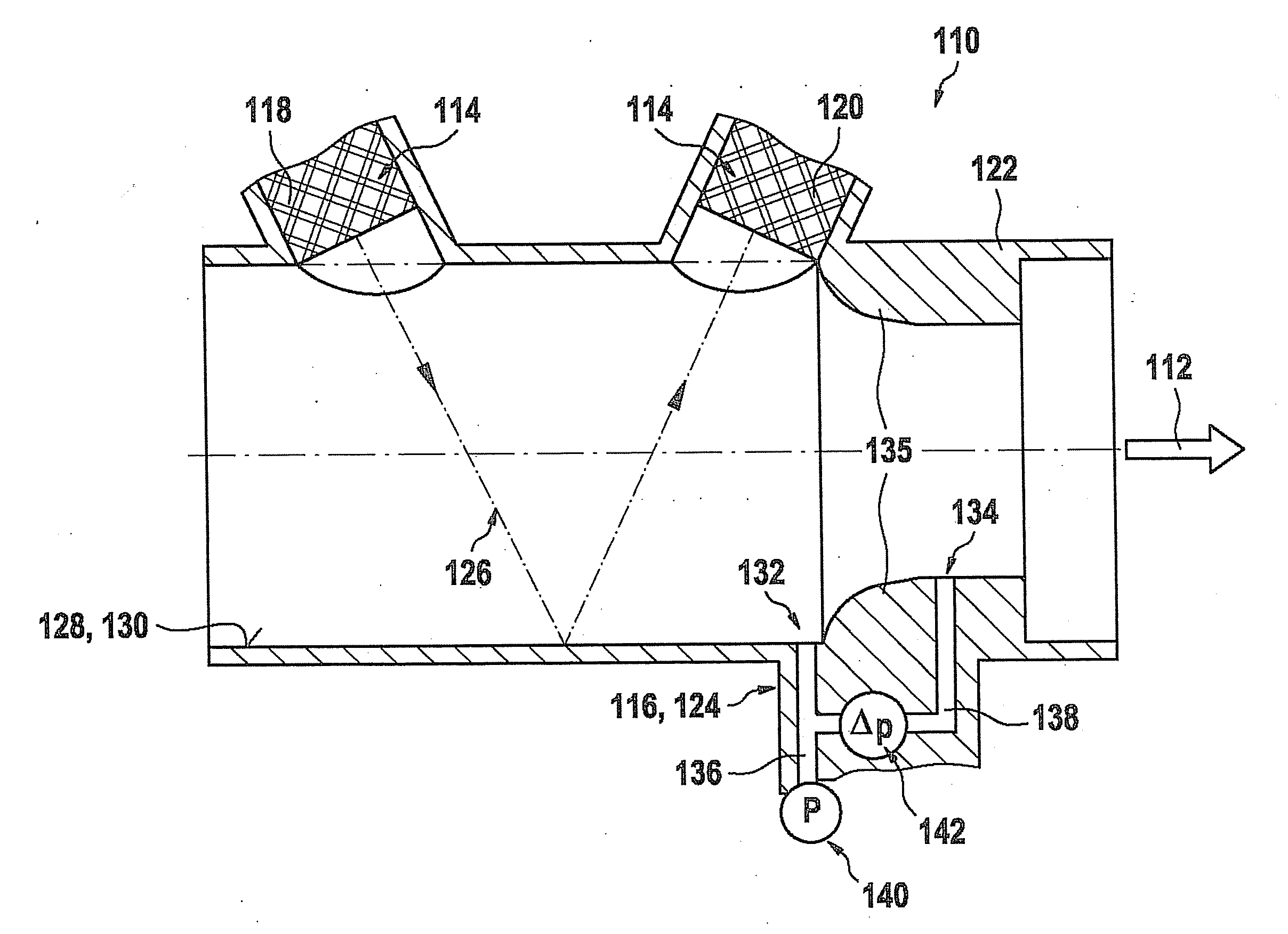
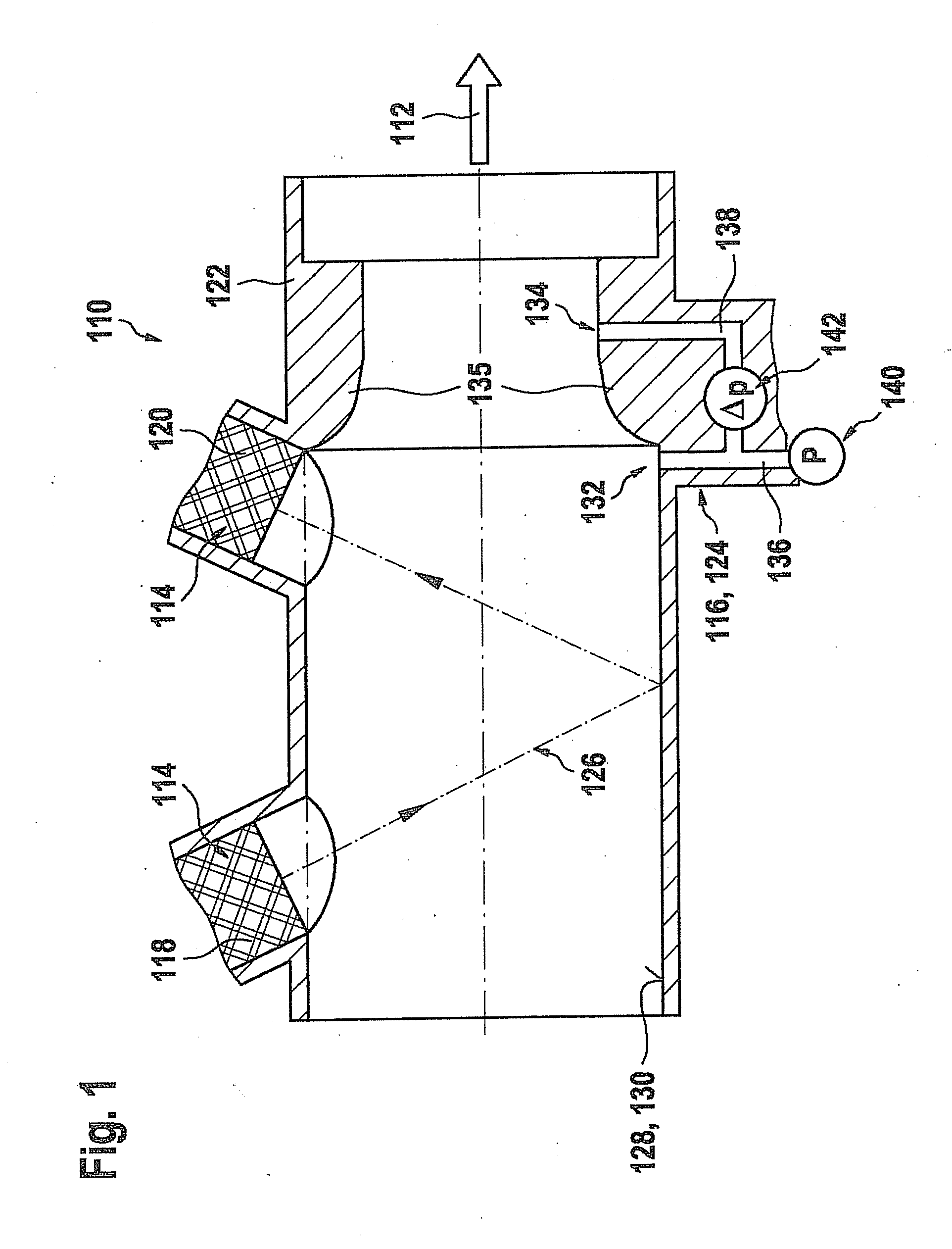
[0025]FIG. 1 shows a first exemplary embodiment of a flowmeter 110 according to the present invention in a sectional diagram parallel to a main direction of flow 112 of a fluid medium. Flowmeter 110 includes a combination of at least one ultrasonic sensor 114 and at least one differential pressure sensor 116. Ultrasonic sensor 114 in the exemplary embodiment shown here includes as an example two ultrasonic transducers 118, which may be situated, for example, in a V-shaped design in a wall of a flow tube 122 through which a fluid medium flows in main direction of flow 112. Differential pressure sensor 116 may be embodied, for example, as a Venturi probe 124 and may also be situated in flow tube 122. Alternatively or in addition to Venturi probe 124, differential pressure sensor 116 may include other types of differential pressure sensors, for example, a measuring aperture.

[0026]In the exemplary embodiment according to FIG. 1, ultrasonic transducers 118, 120 are situated offset from o...


PUM


Abstract

A flowmeter for detecting at least one property of a fluid medium flowing through a flow tube, in particular a flow property, is described. The flowmeter has at least one ultrasonic sensor for detecting at least one first flow property of the fluid medium. In addition, the flowmeter has at least one differential pressure sensor for detecting at least one second flow property of the fluid medium.

Description

CROSS REFERENCE[0001]The present application claims the benefit under 35 U.S.C. §119 of German Patent Application No. DE 102010040396.2 filed on Sep. 8, 2010, which is expressly incorporated herein by reference in its entirety.BACKGROUND INFORMATION[0002]In many fields of technology and natural sciences, fluid media must be supplied to or removed from a process at a predetermined or controlled rate. For this purpose, flowmeters which are equipped to measure a volume or mass flow of the fluid medium are used in particular. According to the measured flow rate, regulating measures may then be performed, for example. An important field of application, although the present invention is not limited thereto, is the field of air flow measuring in automotive engineering. For example, a quantity of intake air supplied to the combustion process may be measured in the intake tract of an internal combustion engine and adjusted through appropriate regulation such as throttle valves, if necessary....

Claims


Application Information

Patent Timeline
Patent Type & Authority Applications(United States)
IPC IPC(8): G01F1/66G01F1/34
CPCG01F1/34G01F1/66G01F1/46G01F1/42
Inventor KONZELMANN, UWE
Owner ROBERT BOSCH GMBH
Why Eureka
Try Eureka