Movable body apparatus, object processing device, exposure apparatus, flat-panel display manufacturing method, and device manufacturing method

Active Publication Date: 2012-03-08
NIKON CORP
View PDF13 Cites 21 Cited by
  • Summary
  • Abstract
  • Description
  • Claims
  • Application Information

AI Technical Summary

Benefits of technology

[0009]According to this apparatus, by the first movable body moving in predetermined strokes in a direction parallel to the first axis, an object held by the first movable body moves in predetermined strokes in a first direction in a state where the object is supported from below. Further, because the second movable body having an object support member moves in a second direction along with the first movable body, the object can be driven arbitrar

Problems solved by technology

Now, in recent years, substrates subject to exposure of exposure apparatuses, especially rectangular shaped glass plates used for liquid crystal displays, tend t

Method used


Image

  • Movable body apparatus, object processing device, exposure apparatus, flat-panel display manufacturing method, and device manufacturing method
  • Movable body apparatus, object processing device, exposure apparatus, flat-panel display manufacturing method, and device manufacturing method
  • Movable body apparatus, object processing device, exposure apparatus, flat-panel display manufacturing method, and device manufacturing method

Examples


first embodiment

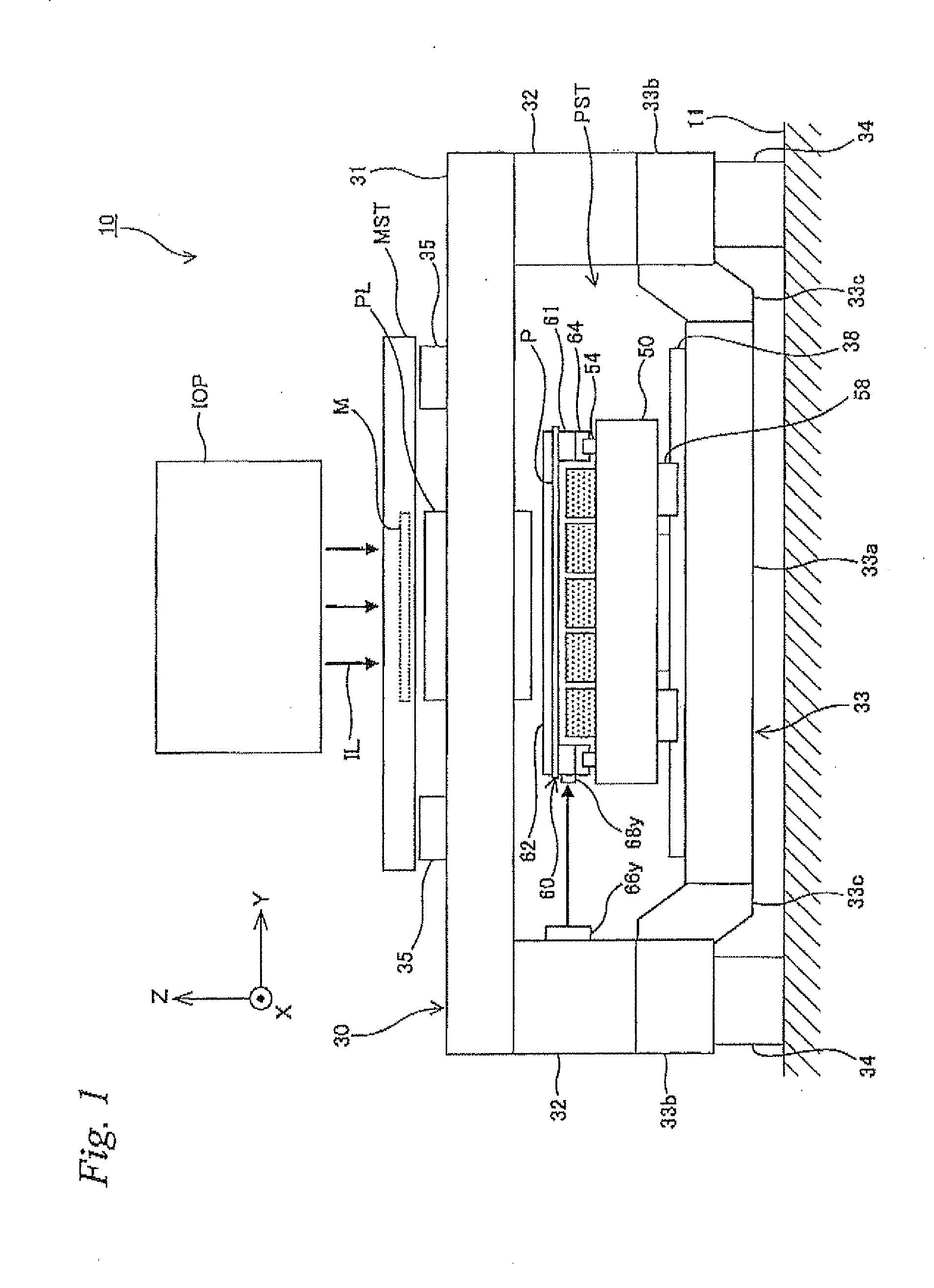
[0032]A first embodiment will be described below, with reference to FIGS. 1 to 8B.

[0033]FIG. 1 schematically shows a configuration of an exposure apparatus 10 related to the first embodiment. Liquid crystal exposure apparatus 10 is a projection exposure apparatus by a step-and-scan method, or a so-called scanner in which a rectangular glass substrate P (hereinafter, simply referred to as a substrate P) that is used in a liquid crystal display device (flat panel display) serves as an exposure subject.

[0034]As shown in FIG. 1, liquid crystal exposure apparatus is equipped with an illumination system OP, a mask stage MST holding a mask M, a projection optical system PL, a device main section 30 supporting mask stage MST, projection optical system PL and the like, a substrate stage device PST holding substrate P, and a control system and the like thereof. In the description below, the explanation is given assuming that a direction in which mask M and substrate P are scanned relative to ...

second embodiment

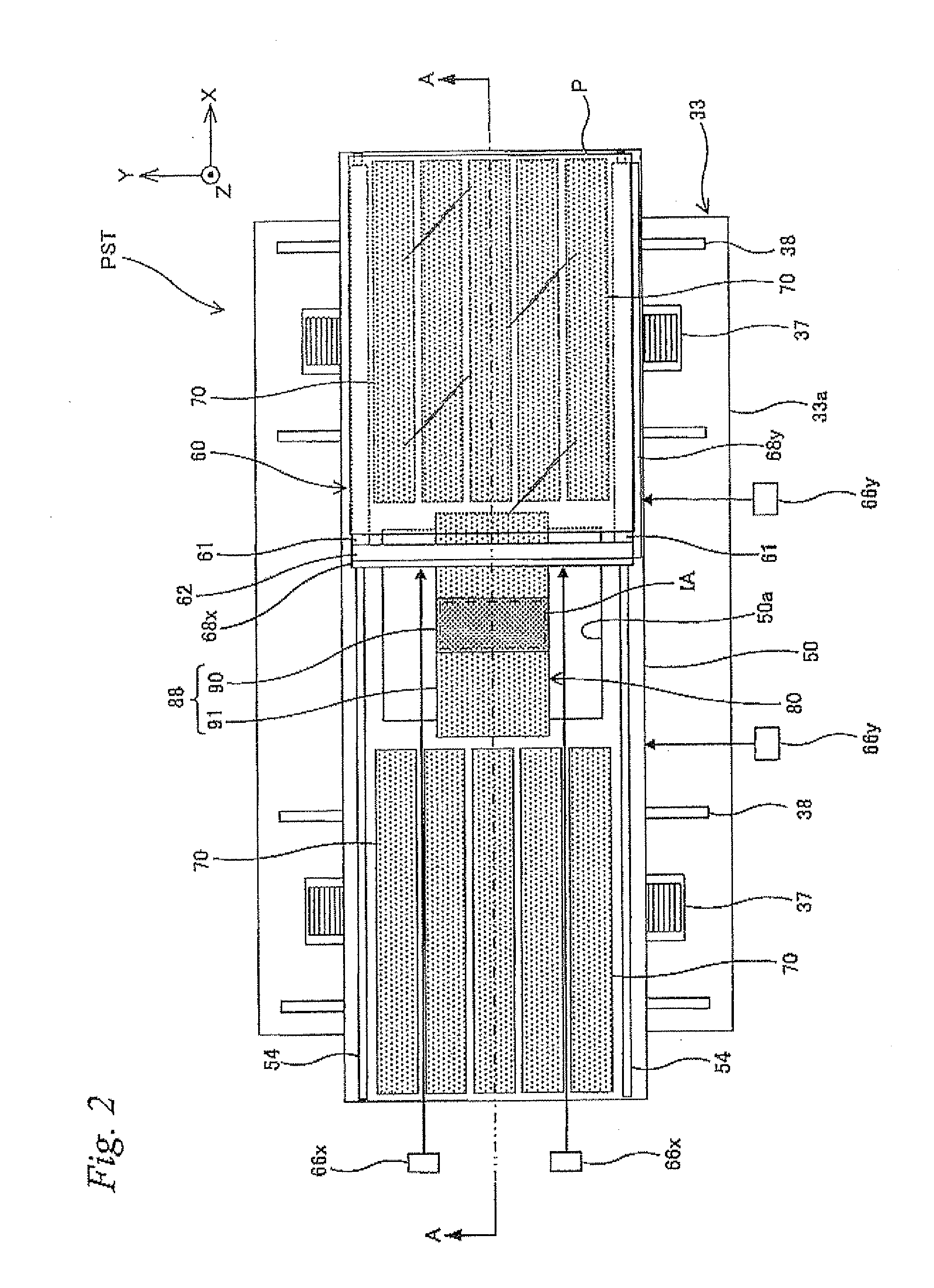
[0083]Next, a substrate stage device related to a second embodiment is described, based on FIGS. 9 and 10. A substrate stage device PSTa of the second embodiment differs on the point that a substrate support member 160 which supports substrate P can be finely driven in the X-axis, the Y-axis, and the θz directions with respect to Y step surface plate 50. Incidentally, in substrate stage device PSTa of this second embodiment, for members that have the same configuration and function as substrate stage device PST (refer to FIG. 2) of the first embodiment described above, the same reference numerals will be used as in the first embodiment described above, and a description thereabout will be omitted.

[0084]Substrate stage device PSTa has a pair of X carriages 20. The pair of X carriages 20 is placed above Y step surface plate 150, on the +Y side and −Y side of substrate support member 160, respectively. Each X carriage 20 consists of a plate shaped member placed parallel to the XY plane...

third embodiment

[0092]Next, a third embodiment will be described, with reference to FIGS. 11 to 13A. In the third embodiment, the configuration of device main section 30 and substrate stage device EST differs from the first embodiment (refer to FIG. 1) described above. Incidentally, in device main section 130 and substrate stage device PSTb of this third embodiment, for members that have the same configuration and function as the first embodiment described above, the same reference numerals will be used as in the first embodiment described above, and a description thereabout will be omitted.

[0093]As shown in FIG. 12B, substrate stage device PSTb related to the third embodiment is mounted on Y step surface plate 50, which is on a mounting 40 set on floor 11. As shown in FIG. 11, substantially the same mounting is provided spaced apart in the X-axis direction as a pair for mounting 40, and Y step surface plate 50 is mounted installed over the two mountings 40. To each of the upper surfaces of the pai...


PUM


Abstract

In a substrate stage device, a substrate is held by a substrate support member mounted on a Y step surface plate. The substrate support member moves in the scanning direction in long strokes on the Y step surface plate. The part corresponding to an exposure area of the substrate is held by suction in a non-contact manner from below by a fixed point stage, and other parts are supported by levitation by the plurality of air floating devices placed on the Y step surface plate. The part corresponding to the exposure area of the substrate is controlled so that surface position of the substrate is located in the depth of focus of the projection optical system by the fixed point stage.

Description

CROSS-REFERENCE TO RELATED APPLICATIONS[0001]This non-provisional application claims the benefit of Provisional Application No. 61 / 380,454 filed Sep. 7, 2010, the disclosure of which is hereby incorporated herein by reference in its entirety.BACKGROUND OF THE INVENTION[0002]1. Field of the Invention[0003]The present invention relates to movable body apparatuses, object processing devices, exposure apparatuses, flat-panel display manufacturing methods, and device manufacturing methods, and more particularly to a movable body apparatus which moves an object along a predetermined two-dimensional plane, an object processing device which performs a predetermined processing on an object held by the movable body apparatus, an exposure apparatus which forms a predetermined pattern on an object held by the movable body apparatus, a flat-panel display manufacturing method which uses the exposure apparatus, and a device manufacturing method which uses the exposure apparatus.[0004]2. Descriptio...

Claims


Application Information

Patent Timeline
IPC IPC(8): G01N21/00
CPCF16C29/025F16C29/008G03F7/709G03F7/70716G03F7/22H01L21/0274H01L21/67092
Inventor AOKI, YASUO
Owner NIKON CORP
Why Eureka
Try Eureka