

Organic electroluminescent display device
a technology of electroluminescent display and electroluminescent light, which is applied in the direction of static indicating devices, discharge tubes luminescent lights, instruments, etc., can solve problems such as shadowing
- Summary
- Abstract
- Description
- Claims
- Application Information
AI Technical Summary
Benefits of technology
Problems solved by technology
Method used
Image

Examples
first embodiment
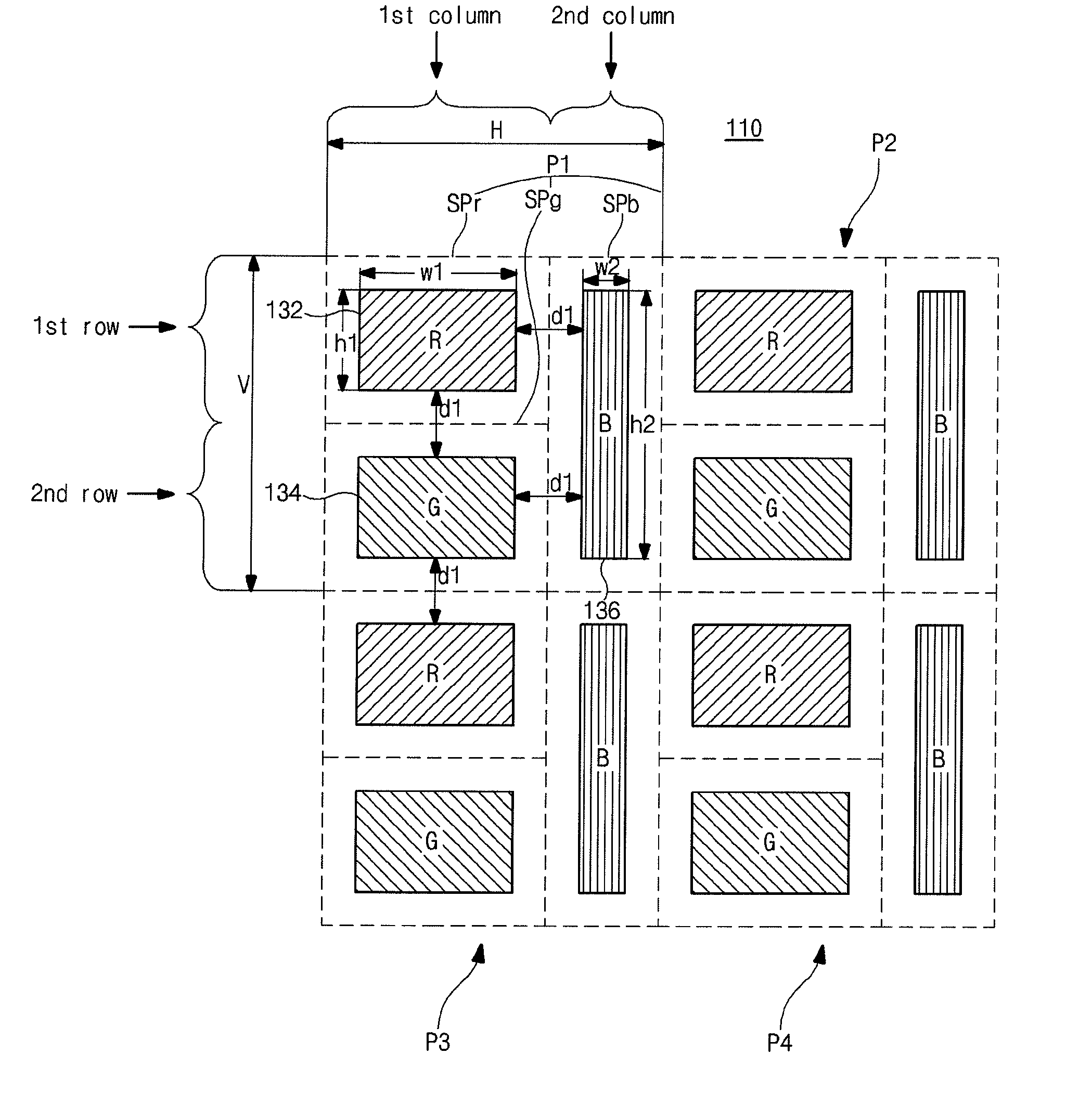
[0041]FIG. 3 is a schematic view showing pixel regions of an OELD device according to the present invention.
[0042]As shown in FIG. 3, an OELD device 110 includes first to fourth pixel regions “P1”, “P2”, “P3” and “P4” arranged in a matrix shape. Each of the first to fourth pixel regions “P1” to “P4” includes red, green and blue sub-pixel regions “SPr”, “SPg” and “SPb”.
[0043]Each of the first to fourth pixel regions “P1” to “P4” has a rectangular shape to have a horizontal length “H” and a vertical length “V”. The red and green sub-pixel regions “SPr” and “SPg” are alternately arranged with each other in a first column of each of the first to fourth pixel regions “P1” to “P4”, and the blue sub-pixel region “SPb” is arranged in a second column of each of the first to fourth pixel regions “P1” to “P4”.
[0044]Each of the first to fourth pixel regions “P1” to “P4” is divided into the first and second columns along a horizontal direction, and the first column is divided into first and seco...
second embodiment
[0086]FIG. 8 is a schematic view showing pixel regions of an OELD device according to the present invention. As shown in FIG. 8, an OELD device 210 includes first to fourth pixel regions “P1” to “P4” arranged in a matrix shape. Each of the first to fourth pixel regions “P1” to “P4” includes red, green and blue sub-pixel regions “SPr”, “SPg” and “SPb”.
[0087]Each of the first to fourth pixel regions “P1” to “P4” has a rectangular shape to have a horizontal length “H” and a vertical length “V”. The red and green sub-pixel regions “SPr” and “SPg” are alternately arranged with each other in a first column of each of the first to fourth pixel regions “P1” to “P4”, and the blue sub-pixel region “SPb” is arranged in a second column of each of the first to fourth pixel regions “P1” to “P4”.
[0088]Each of the first to fourth pixel regions “P1” to “P4” is divided into the first and second columns along a horizontal direction, and the first column is divided into first and second rows along a ve...
third embodiment
[0103]FIG. 10 is a schematic view showing pixel regions of an OELD device according to the present invention. As shown in FIG. 10, an OELD device 310 includes first to fourth pixel regions “P1” to “P4” arranged in a matrix shape. Each of the first to fourth pixel regions “P1” to “P4” includes red, green and blue sub-pixel regions “SPr”, “SPg” and “SPb”.
[0104]Each of the first to fourth pixel regions “P1” to “P4” has a rectangular shape to have a horizontal length “H” and a vertical length “V”. The red and green sub-pixel regions “SPr” and “SPg” are alternately arranged with each other in a first column of each of the first to fourth pixel regions “P1” to “P4”, and the blue sub-pixel region “SPb” is arranged in a second column of each of the first to fourth pixel regions “P1” to “P4”.
[0105]Each of the first to fourth pixel regions “P1” to “P4” is divided into the first and second columns along a horizontal direction, and the first column is divided into first and second rows along a ...
PUM
 Abstract
Description
Claims
Application Information