Well Buoyancy Elevator and Conveyor Power Apparatus and Method

a technology of elevators and conveyors, which is applied in the direction of machines/engines, renewable energy generation, greenhouse gas reduction, etc., can solve the problems of cutting the power needed to inject air into the bottom of the well, and achieves the effects of reducing the risk of accidents, increasing the power output, and avoiding pollution

Inactive Publication Date: 2012-03-15
RIZZI JOSEPH
View PDF7 Cites 11 Cited by
  • Summary
  • Abstract
  • Description
  • Claims
  • Application Information

AI Technical Summary

Benefits of technology

[0005]It is an object of the current invention to provide a power generation and energy storage system that is safe, non-polluting, and aesthetically neutral or pleasing. Wells dug in the ground offer many great advantages like: able to be located near power needs, deeper and wider wells allow for more power output and / or longer power cycles. Wells are easily dug and lined to hold water acting as a cheap stable container. Conveyors allow for continuous power generation and can easily be scaled up by the size of the buckets and depth of the well. Elevators are the simplest design and are great at storing up power and delivering this power at peak demand times. Multiple elevator type designs can be joined to obtain continuous power. The well may be sealed airtight and pressurized to at or near the pressures found at the bottom of the well, which drastically cuts the power needed to inject the air into water at the bottom of the well. Circulating a gas like air or helium from the top of the well to the bottom of the well would be done naturally due to pressure changes which will occur when an air moving and / or compression type device located at the bottom of the well close to the gas exit moves the gas from the pressurized chamber into the liquid which the gas would then proceed upward into the buoyancy container and displace the water in the buoyancy container.

Problems solved by technology

The well may be sealed airtight and pressurized to at or near the pressures found at the bottom of the well, which drastically cuts the power needed to inject the air into water at the bottom of the well.

Method used


Image

  • Well Buoyancy Elevator and Conveyor Power Apparatus and Method
  • Well Buoyancy Elevator and Conveyor Power Apparatus and Method
  • Well Buoyancy Elevator and Conveyor Power Apparatus and Method

Examples


Embodiment Construction

[0025]Various embodiments of the invention will now be described with reference to the drawings.

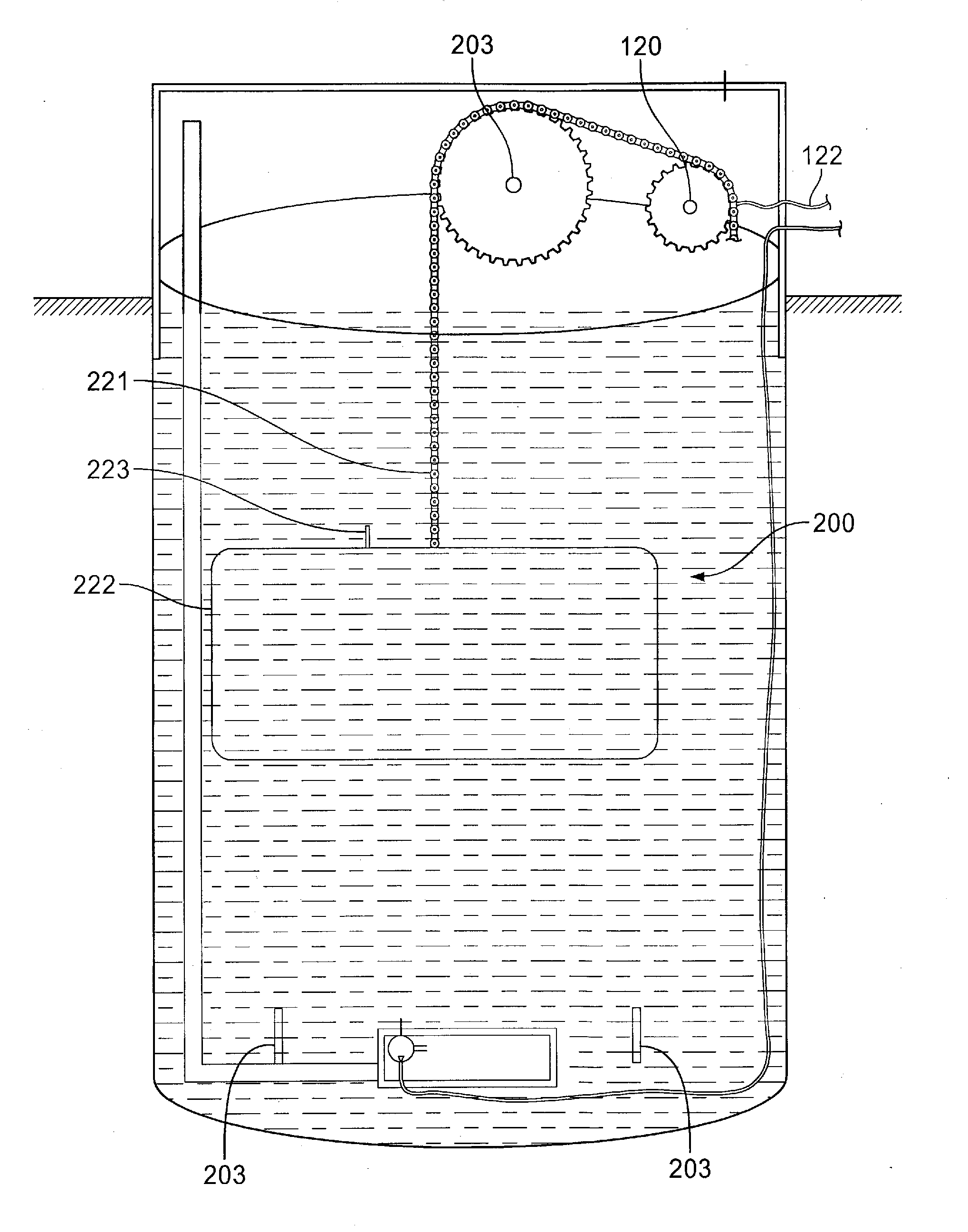
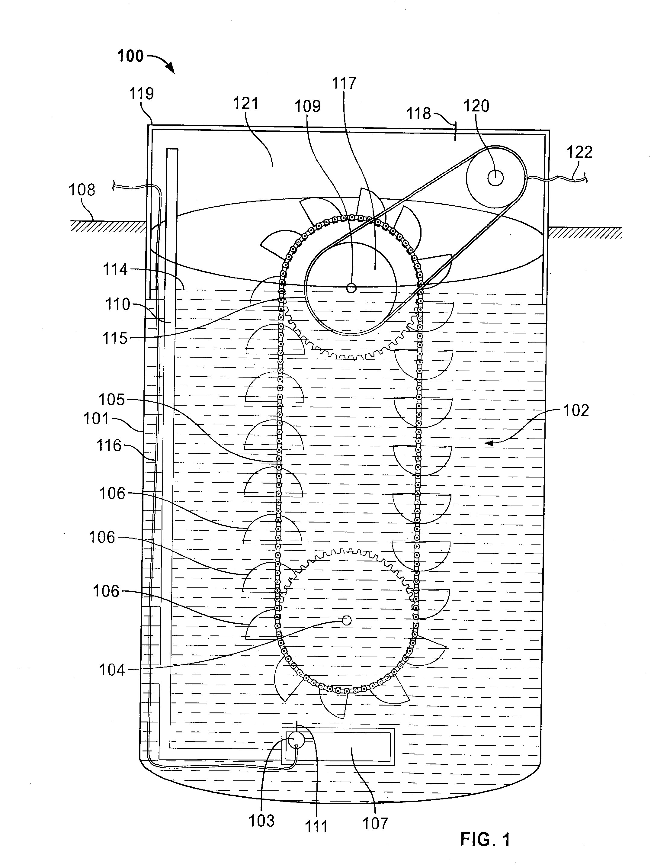
[0026]In an embodiment as shown in FIG. 1, a well buoyancy power system 100 comprises a well 101 adapted to hold a liquid; a buoyancy engine substantially contained in said well; a generator 120 coupled to said buoyancy engine; and an air mover 103 for transmitting a pressurized gas at the lower part of the well into the liquid. In certain aspects, the well is sealed to contain a gas and pressure inside the well, which can be done by employing a gas-tight cap 119 at the top of the well. The well may be equipped with a valve device 118 to allow the gas to be charged into the well and to allow gas to be discharged from the well. The gas discharge mechanism may also be a separate device from the valve device 118. There is an air space 121 above the liquid level. The air mover 103 may be a piston compressor, a diaphragm compressor, a turbo air compressor, a centrifugal air compressor, a blowe...


PUM


Abstract

Systems and methods for generating, converting, and/or storing power under the ground level are disclosed. A well buoyancy power system includes a well adapted to hold a liquid and sealed to hold a pressurize gas, a buoyancy engine that can be a conveyor buoyancy engine or an elevator buoyancy engine, a generator coupled to the buoyancy engine, and an air mover located in the bottom air chamber to transmit the pressurized gas into the liquid at the lower part of the well to drive the buoyancy engine. The system may not be sealed and pressurized for cheaper storage of air when not reused. Because the system utilizes underground space, it is safe, low or no noise, non-polluting, and aesthetically neutral for deployment near where power is to be used such as population centers.

Description

CROSS REFERENCE TO RELATED APPLICATIONS[0001]This application claims the benefit of priority of U.S. Provisional Patent Application No. 61381112 filed Sep. 9, 2010, which is incorporated herein by reference in its entirety.BACKGROUND[0002]Low cost, safe and environmentally friendly power has been a long time goal, and renewable energy is one of the solutions that have gained increased emphasis. Where renewable energy sources such as wind power and solar power are the predominant sources, energy storage is required because the peak energy generating time may mismatch with energy consumption time. Additionally, energy storage may be required to smooth out the fluctuation in renewable energy generation and power consumption.[0003]Among energy storage methods that do not use chemical mechanisms, buoyancy power generation / storage and compressed air energy storage systems are known. For example, U.S. patent application Ser. No. 12 / 614,183 describes an energy generation and storage system ...

Claims


Application Information

Patent Timeline
Patent Type & Authority Applications(United States)
IPC IPC(8): F03B17/02F03B13/00
CPCF03B11/002F03B17/025Y02E10/226Y02E10/20F03B17/04Y10T137/86051
Inventor RIZZI, JOSEPH
Owner RIZZI JOSEPH
Why Eureka
Try Eureka