
Welding systems and methods

Inactive Publication Date: 2012-03-15
HONEYWELL INT INC
View PDF5 Cites 6 Cited by
  • Summary
  • Abstract
  • Description
  • Claims
  • Application Information

AI Technical Summary

Benefits of technology

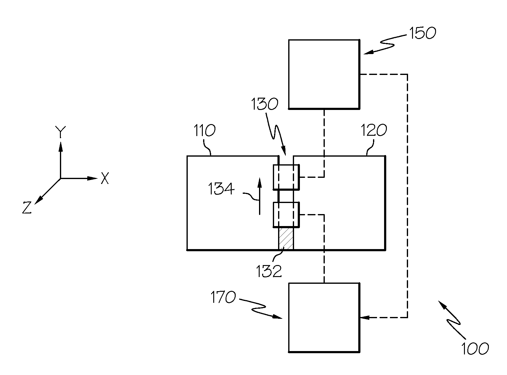
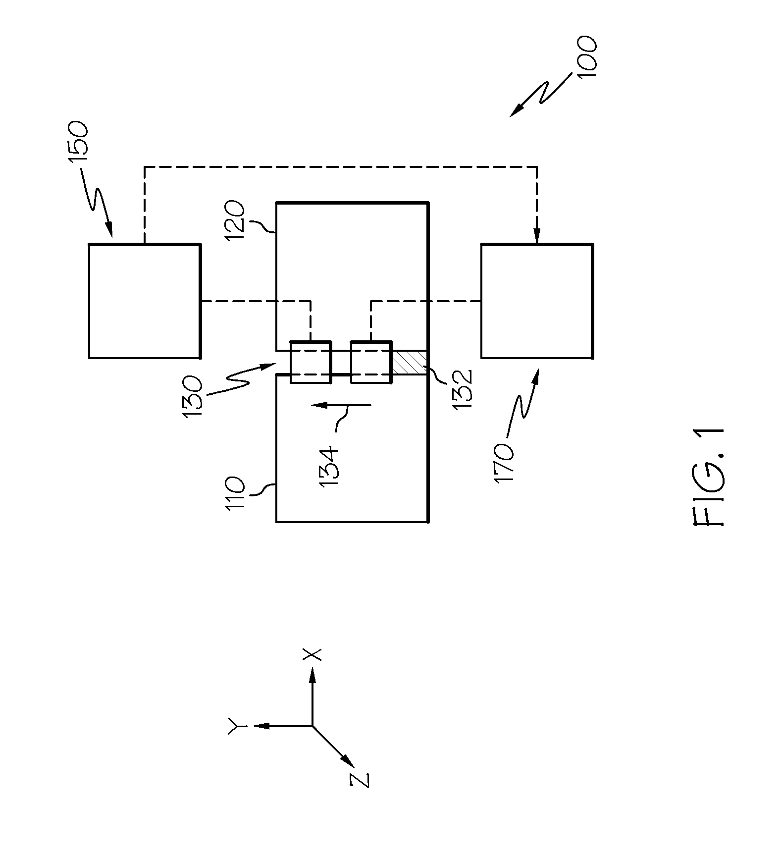
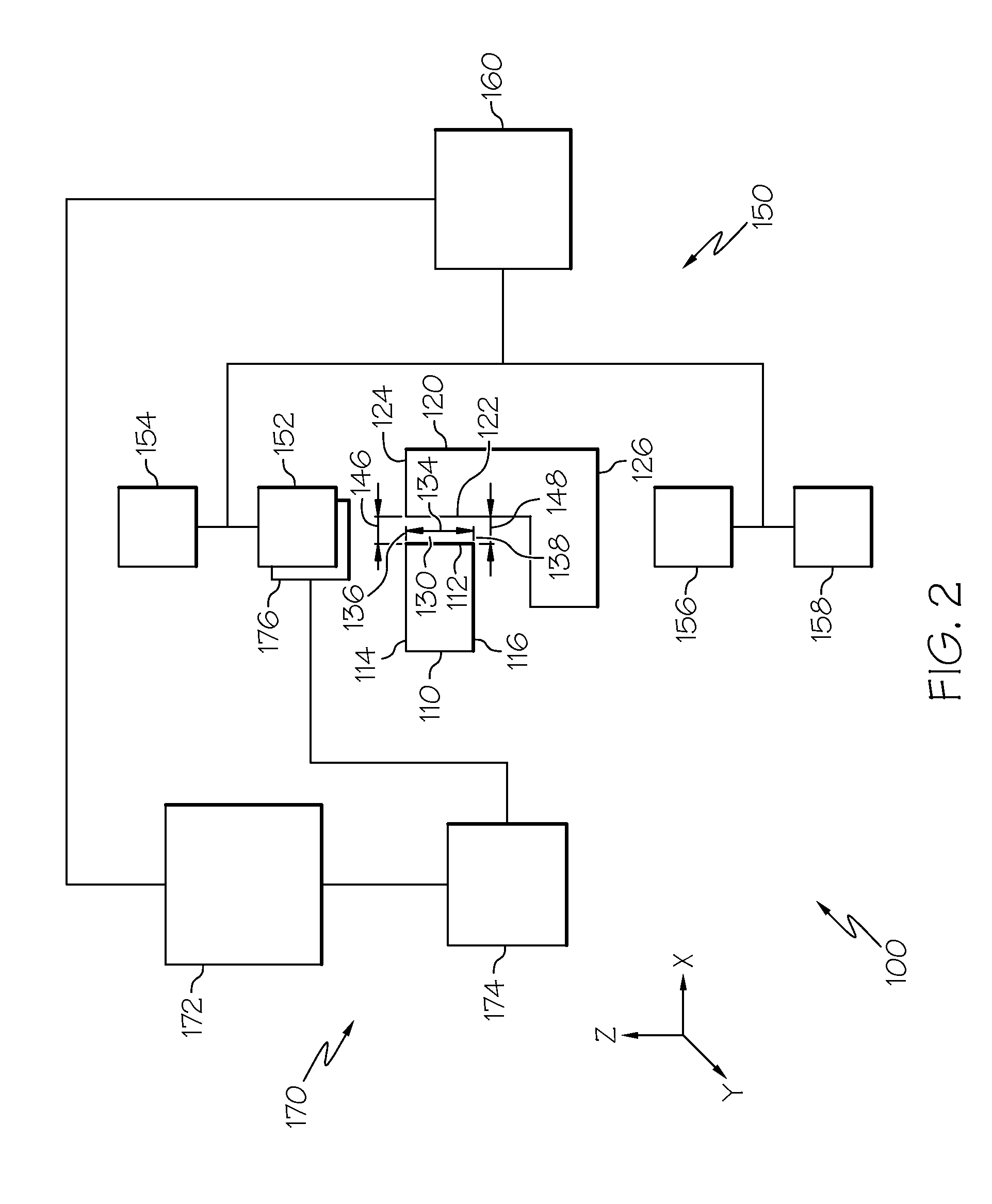
[0017]Broadly, exemplary embodiments discussed herein are directed to welding systems and methods for welding a joint between first and second work pieces. The welding system includes a sensor system and a beam system. A weld face sensor of the s

Problems solved by technology

Imprecise positioning of the welding beam may result in an unsatisfactory weld, and the quality of the weld may impact many aspects of the completed part, including the microstructure, microhardness, tensile properties, formability, fatigue strength, fracture toughness, and the overall value of the joining process.
These systems, however, often lose contact with the joint, which can interrupt the operation of the tracking device and compromise the weld quality.
However, optical imaging may be sensitive to the level of ambient light and smoke emitted by the welding process, and subjective evaluations of the visual image to be tracked may also be an issue.
An additional problem with many tracking devices includes the difficulty of positioning the sensors at inaccessible portions of the joint.

Method used


Image

  • Welding systems and methods
  • Welding systems and methods
  • Welding systems and methods

Examples


Embodiment Construction

[0016]The following detailed description is merely exemplary in nature and is not intended to limit the invention or the application and uses of the invention. As used herein, the word “exemplary” means “serving as an example, instance, or illustration.” Thus, any embodiment described herein as “exemplary” is not necessarily to be construed as preferred or advantageous over other embodiments. All of the embodiments described herein are exemplary embodiments provided to enable persons skilled in the art to make or use the invention and not to limit the scope of the invention which is defined by the claims. Furthermore, there is no intention to be bound by any expressed or implied theory presented in the preceding technical field, background, brief summary, or the following detailed description.

[0017]Broadly, exemplary embodiments discussed herein are directed to welding systems and methods for welding a joint between first and second work pieces. The welding system includes a sensor ...


PUM

PropertyMeasurementUnit
Thicknessaaaaaaaaaa
Angleaaaaaaaaaa

Abstract

A welding system is provided for welding a first work piece to a second work piece at a joint having a weld face and a root face. The welding system includes a weld face sensor configured to determine first joint characteristics at the weld face; a root face sensor configured to determine second joint characteristics at the root face; a controller coupled to the weld face sensor and the root face sensor and configured to generate positioning signals based on the first joint characteristics and the second joint characteristics; and a welding gun coupled to the controller and positioned proximate to the weld face, the welding gun configured to generate a welding beam for welding the joint based on the positioning signals from the controller.

Description

TECHNICAL FIELD[0001]The present invention generally relates to welding systems and methods, and more particularly relates to welding systems and methods for tracking a joint between two or more work pieces to be welded.BACKGROUND[0002]High energy beam welding, such as laser beam or electron beam welding, is used to join one work piece to another work piece by directing a highly focused beam of energy into a joint between the work pieces to heat and fuse them together. One common type of welding joint is a butt joint in which an edge portion of one work piece is placed in abutting fashion generally against an edge portion of another work piece before welding the edges together.[0003]Exact positioning of the welding beam relative to the joint is essential for a high-quality weld, particularly as the welding beam travels along the joint during the welding process. As examples of imprecise positioning, the welding beam may be laterally offset with the joint, at an incorrect angle relat...

Claims


Application Information

Patent Timeline
IPC IPC(8): B23K9/00G01M19/00G01B21/08G01B7/00
CPCB23K26/036B23K26/045B23K26/24B23K26/0869B23K15/002B23K15/006B23K15/0013B23K26/044B23K26/0342
Inventor SAUNDERS, JACKHOGAN, ROBERTSINGH, SURENDRAKINNEY, ANDYEASTERWOOD, RANDAL
Owner HONEYWELL INT INC
Features
  • Generate Ideas
  • Intellectual Property
  • Life Sciences
  • Materials
  • Tech Scout
  • Unparalleled Data Quality
  • Higher Quality Content
  • 60% Fewer Hallucinations
Learn More