Johnson ambient-heat engine

a technology of ambient heat and engine, which is applied in the direction of electrochemical generators, circuit arrangements, safety/protection circuits, etc., can solve the problems of difficult access, difficult to achieve efficient operation, and difficulty in creating significant temperature differences between components, and achieves low energy consumption and high voltage.

Active Publication Date: 2012-03-15
JTEC ENERGY INC
View PDF3 Cites 41 Cited by
  • Summary
  • Abstract
  • Description
  • Claims
  • Application Information

AI Technical Summary

Benefits of technology

[0009]According to an embodiment of the present invention, an electrochemical conversion system has a thermally-conductive housing. The interior of the housing is divided into a high-pressure chamber and a low-pressure chamber by a substantially gas-impermeable membrane. An ionically-conductive, electrical-energy-generating mechanism forms at least a portion of the substantially gas-impermeable membrane. A first hydrogen-storage medium is disposed within the high-pressure chamber. A second hydrogen-storage medium is disposed within the low-pressure chamber. The characteristics of the hydrogen-storage mediums are such that at any given temperature, the first hydrogen-storage medium stores hydrogen at a first average storage pressure that is higher than a second average storage pressure at which the second hydrogen-storage medium stores hydrogen. The housing contains an initial quantity of hydrogen. An electrical-energy storage device connected to the ionically-conductive, electrical-energy-generating mechanism is selectively operable between a charge condition and a discharge condition.
[0010]The Johnson Ambient-Heat Engine (JANE) (an electrochemical conversion system) uses thermal transients that naturally occur in its ambient environment to generate electrical power. During selected periods of high temperature, the electrochemical conversion system naturally produces a high voltage output for a given pressure ratio between the high-pressure and low-pressure chambers. The electrical-energy storage device is charged by allowing hydrogen to expand from the high-pressure chamber into the low-pressure chamber during periods of high temperature and thereby high voltage. Conversely, the electrochemical conversion system produces low voltage during periods of low temperature. The electrical-energy storage device is discharged during selected low voltage periods to compress hydrogen from the low-pressure chamber back into the high-pressure chamber. Given two electrons per hydrogen molecule, returning the hydrogen to the high-pressure chamber requires the same amount of current as that generated when it transitioned to the low-pressure chamber. However, less energy is required since the hydrogen is returned during periods when the voltage of the electrochemical conversion system is low. The difference in energy produced during high-temperature expansion versus low temperature-compression is retained within the electrical-energy storage device and is available for supply to an external load.

Problems solved by technology

A heat-source and heat-sink pair having two distinct, spaced-apart temperatures typically does not occur naturally and / or plentifully, and thus are generally difficult to access.
A major limitation in achieving efficient operation is associated with the difficulty of creating a significant temperature difference between components.
The close proximity of the components in a small device allows parasitic heat transfer losses between the two metal-hydride beds that are too high whenever a significant temperature gradient is present.
In larger devices, the need for insulation and heat sink / source material can result in a large, bulky device that is difficult to implement.

Method used


Image

  • Johnson ambient-heat engine
  • Johnson ambient-heat engine
  • Johnson ambient-heat engine

Examples


Embodiment Construction

[0021]Embodiments of the present invention are described herein. The disclosed embodiments are merely exemplary of the invention that may be embodied in various and alternative forms, and combinations thereof. As used herein, the word “exemplary” is used expansively to refer to embodiments that serve as illustrations, specimens, models, or patterns. The figures are not necessarily to scale and some features may be exaggerated or minimized to show details of particular components. In other instances, well-known components, systems, materials, or methods have not been described in detail in order to avoid obscuring the present invention. Therefore, at least some specific structural and functional details disclosed herein are not to be interpreted as limiting, but merely as a basis for the claims and as a representative basis for teaching one skilled in the art to variously employ the present invention.

Overview

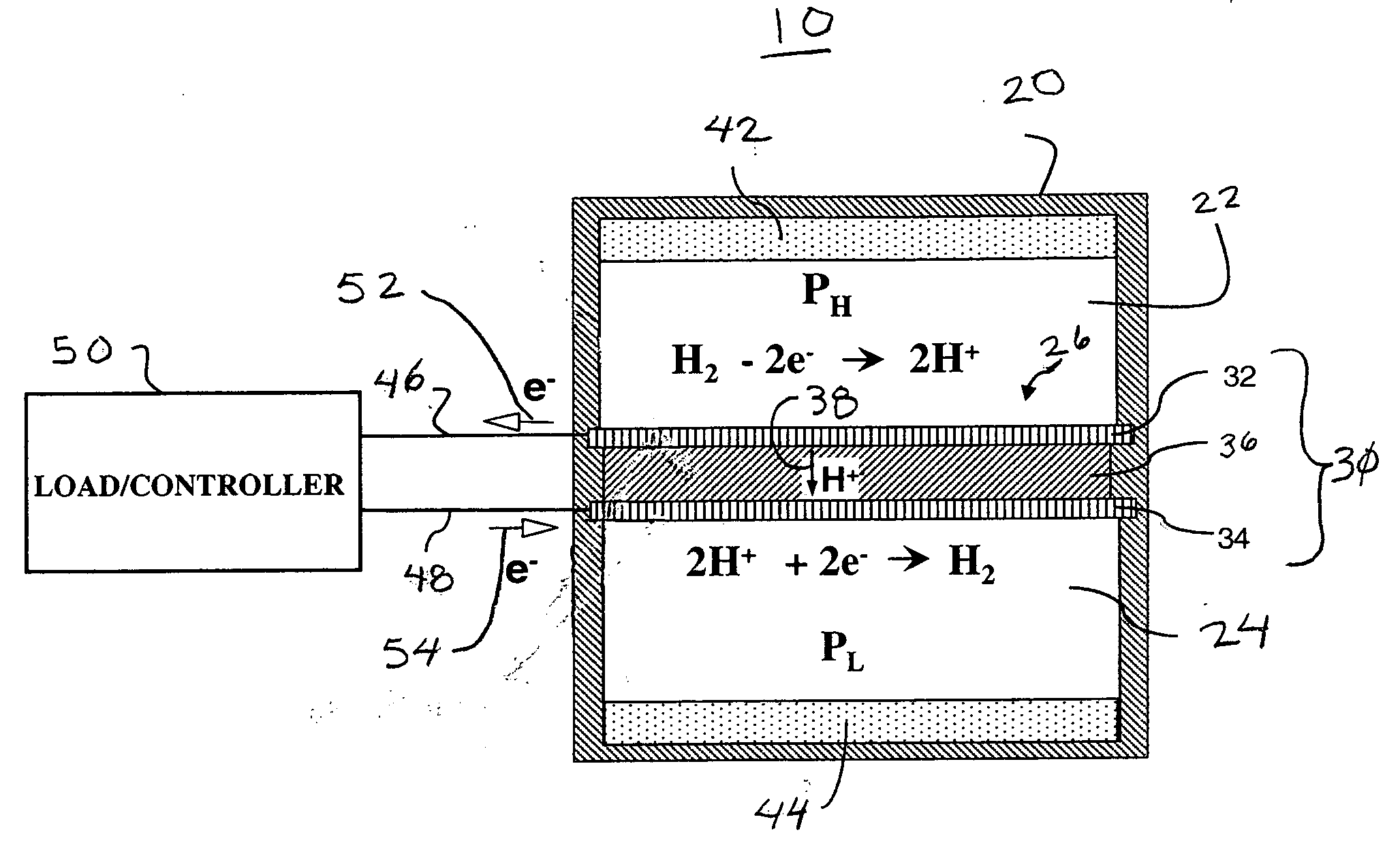
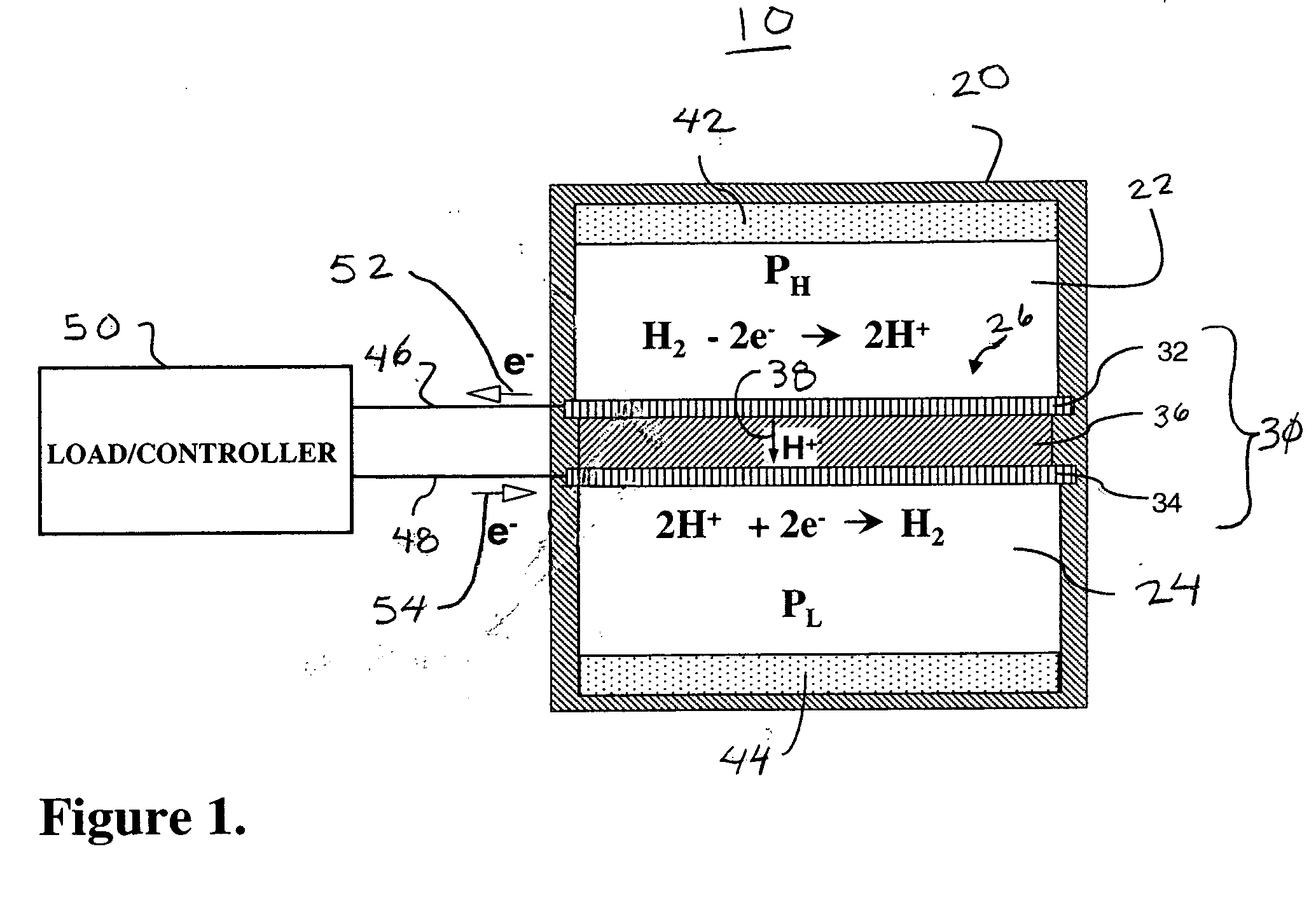
[0022]As an overview, the invention teaches a system and methodology for gen...


PUM

PropertyMeasurementUnit
thermally-conductiveaaaaaaaaaa
pressureaaaaaaaaaa
electrical-energyaaaaaaaaaa

Abstract

An ambient-heat engine has a substantially thermally-conductive housing whose interior is divided into a high-pressure chamber and a low-pressure chamber by a substantially gas-impermeable barrier. An ionically-conductive, electrical-energy-generating mechanism forms at least a portion of the barrier. First hydrogen-storage medium is disposed within the high-pressure chamber and second hydrogen-storage medium is disposed within the low-pressure chamber. An electrical-energy storage device connected to the ionically-conductive, electrical-energy-generating mechanism is operable between a charge condition and a discharge condition. In a charge condition, hydrogen atoms within the high-pressure chamber are converted to hydrogen ions and conducted through the electrical-energy-generating mechanism to the low-pressure chamber causing electrical-energy to be generated to the electrical-energy storage device. When the electrical-energy storage device is in a discharge condition an electric current is passed through the electrical-energy-generating mechanism causing hydrogen in the low-pressure chamber to convert to hydrogen ions and conduct through the electrical-energy-generating mechanism to the high-pressure chamber.

Description

RELATED APPLICATIONS[0001]Not applicable.STATEMENT REGARDING FEDERALLY-SPONSORED RESEARCH OR DEVELOPMENT[0002]Not applicable.TECHNICAL FIELD[0003]This invention relates to energy harvesting mechanisms for generating electrical power, and more particularly, the invention relates to a thermo-electrochemical device that utilizes hydrogen to convert heat energy from an environment in which the device is located into electrical power.BACKGROUND OF THE INVENTION[0004]It has long been a goal to develop an engine that operates on thermal energy that is freely available in the ambient environment. Consistent with the second law of thermodynamics, prior attempts at such thermal-energy-harvesting devices required two distinct sources of thermal energy, namely, a heat source and a heat sink for supplying and removing heat, respectively, at different temperatures simultaneously. A heat-source and heat-sink pair having two distinct, spaced-apart temperatures typically does not occur naturally and...

Claims


Application Information

Patent Timeline
Patent Type & Authority Applications(United States)
IPC IPC(8): H01M8/06
CPCH01M8/04104H01M8/04208H01M8/04216H01M8/04365H01M8/04388B01J2219/0805H01M8/04955H01M8/065Y02E60/50B01J19/088H01M8/04552Y02E60/10H02J7/00306H01M8/04074H01M8/04201H01M14/00H01M16/003H01M16/006H02J7/345
Inventor JOHNSON, LONNIE G.
Owner JTEC ENERGY INC
Why Eureka
Try Eureka