High-frequency switching circuit and radio communication device

a high-frequency switching and radio communication technology, applied in the direction of coupling devices, electrical equipment, transmission, etc., can solve the problems of increased parasitic capacitance, difficult to lay out, and deterioration of operating characteristics

Inactive Publication Date: 2012-03-15
KK TOSHIBA
View PDF3 Cites 11 Cited by
  • Summary
  • Abstract
  • Description
  • Claims
  • Application Information

AI Technical Summary

Problems solved by technology

However, there is a problem that parasitic capacitance is increased when the gate width is increased.
Large parasitic capacitance increases leakage current, which leads to deterioration in operating characteristics.
Further, there is a problem that the high-frequency switching circuit having the above structure is difficult to lay out and increases circuit area when being applied to a radio communication device having a differential structure.

Method used


Image

  • High-frequency switching circuit and radio communication device
  • High-frequency switching circuit and radio communication device
  • High-frequency switching circuit and radio communication device

Examples


first embodiment

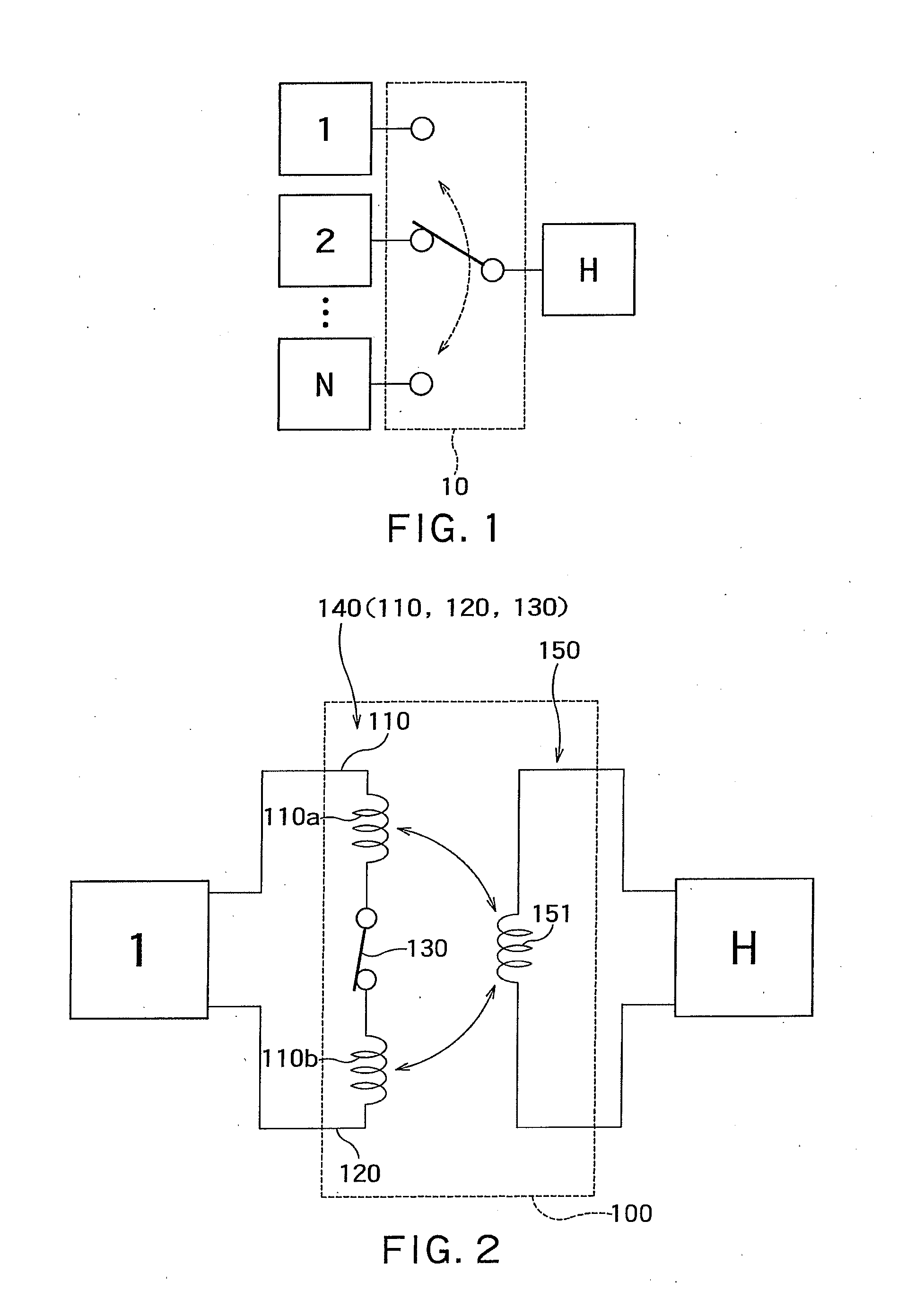
[0021]FIG. 1 shows a functional image of a high-frequency switching circuit.

[0022]A high-frequency switching circuit 10 switches the connection between a high-frequency circuit H and high-frequency circuits 1, 2, . . . , N.

[0023]N is an integer of 1 or greater. When N is 1, the high-frequency switching circuit 10 switches the connection and disconnection between two high-frequency circuits (high-frequency circuit H and high-frequency circuit 1).

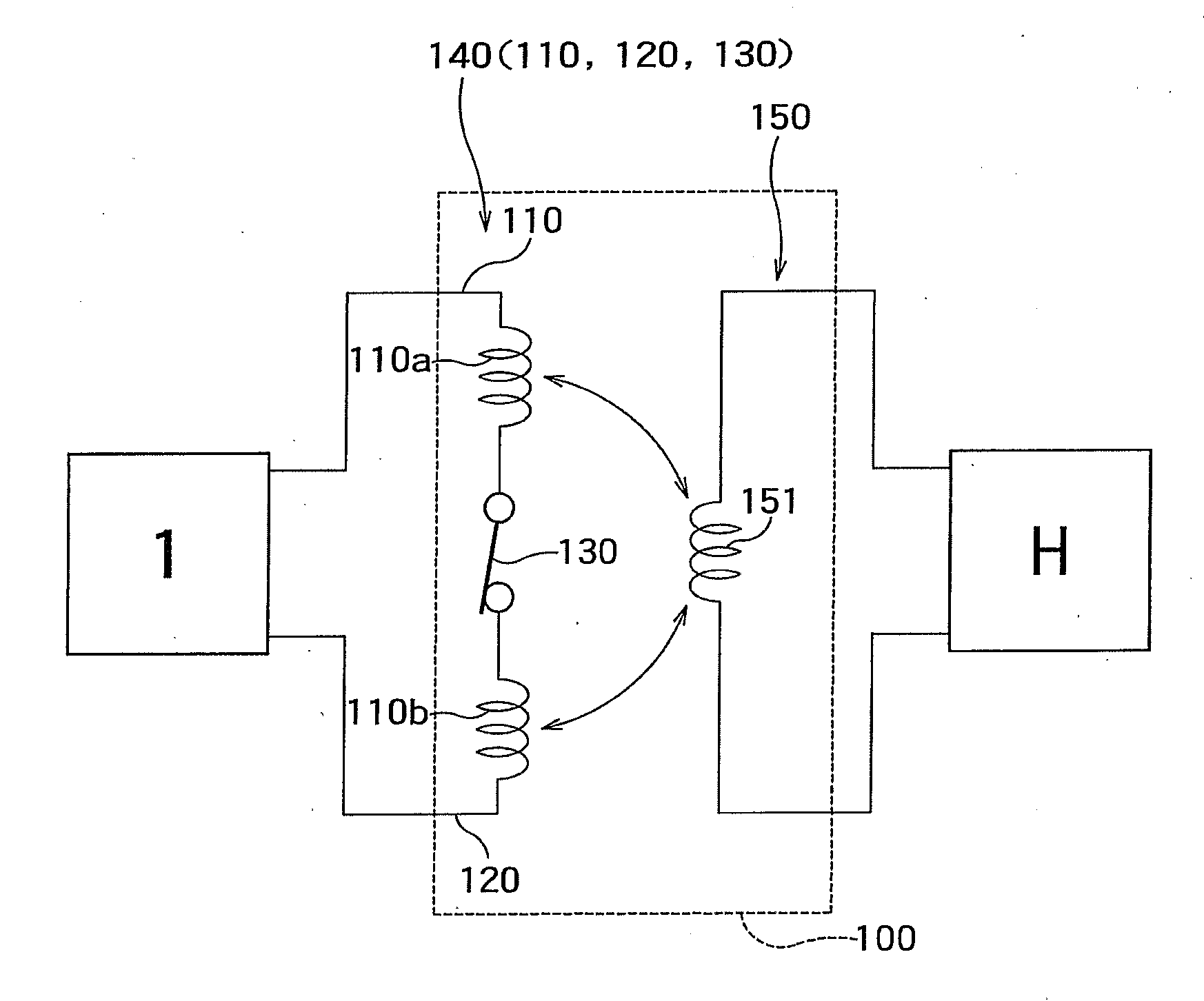
[0024]FIG. 2 shows a structural example of a high-frequency switching circuit according to the first embodiment (when N is 1).

[0025]A high-frequency switching circuit 100 of FIG. 2 performs control to switch the connection and disconnection between the high-frequency circuits 1 and H.

[0026]The high-frequency switching circuit 100 includes a first differential line 140 and a third line 150.

[0027]The first differential line 140 includes a first line 110, a second line 120, and a switch (first switch) 130.

[0028]The first line 110 has one end and...

second embodiment

[0052]The first embodiment shows a high-frequency switching circuit when N is 1. In the present embodiment, a high-frequency switching circuit when N is 2 will be explained.

[0053]FIG. 4 shows a high-frequency switching circuit according to the second embodiment. Components similar to those of FIG. 2 are attached with the same symbols.

[0054]In the block diagram of FIG. 4, a second differential line 240 and a high-frequency circuit 2 are additionally arranged.

[0055]The second differential line 240 is formed similarly to the first differential line 140.

[0056]That is, the second differential line 240 includes a fourth line 210, a fifth line 220, and a switch (second switch) 230.

[0057]The fourth line 210 has one end and the other end. The fourth line 210 includes an inductor pattern (fourth inductor) 210a.

[0058]The fifth line 220 has one end and the other end. The fifth line 220 includes an inductor pattern (fifth inductor) 210b.

[0059]The other ends of the fourth line 210 and the fifth...

third embodiment

[0076]FIG. 7 shows a radio communication device according to the third embodiment.

[0077]This radio communication device includes: the high-frequency switching circuit 200 of FIG. 4 according to the second embodiment; a transmitter front-end circuit 1100; a receiver front-end circuit 1200; a oscillator circuit 1300; and a loop antenna 1400.

[0078]The transmitter front-end circuit 1100 corresponds to the high-frequency circuit 1 of FIG. 4. The receiver front-end circuit 1200 corresponds to the high-frequency circuit 2. Further, the loop antenna 1400 corresponds to the high-frequency circuit H.

[0079]The transmitter front-end circuit 1100 includes: a lowpass filter 1101; a mixer 1102; and a differential power amplifier (first amplifier) 1103.

[0080]The differential output terminals of the differential power amplifier 1103 are connected to both ends of the differential line 140 (that is, the other end of the first line 110 and the other end of the second line 120).

[0081]The mixer 1102 up-c...


PUM


Abstract

According to one embodiment of the present invention, there is provided a high-frequency switching circuit including a first differential line and third line. The differential line includes a first line configured to have one end and an other end, a second line configured to have one end and an other end and a first switch configured to switch electrical connection between the one ends of the first and second lines. The differential line receives or outputs differential signals by the other ends of the first and second lines. The third line is configured to be electromagnetically coupled with the first differential line when the first switch is turned on. The first switch is arranged at a position where an electrical length from the other end of the first line and an electrical length from the other end of the second line are approximately equal.

Description

CROSS REFERENCE TO RELATED APPLICATIONS[0001]This application is based upon and claims the benefit of priority from the prior Japanese Patent Application No. 2010-201976, filed on Sep. 9, 2010, the entire contents of which are incorporated herein by reference.FIELD[0002]The embodiments of the present invention relate to a high-frequency switching circuit for switching the connection between high-frequency circuits, and a radio communication device using the high-frequency switching circuit.RELATED ARTBackground[0003]A conventional high-frequency switching circuit is formed of a plurality of MOS switches (MOS transistors) for switching the connection between circuits, and shunt MOS switches corresponding to the MOS switches, for example. As another example, there is also a high-frequency switching circuit formed of transformers and shunt MOS switches.[0004]When the gate width of the MOS switch is increased, ON resistance is reduced and suitable loss characteristics can be obtained.[0...

Claims


Application Information

Patent Timeline
Patent Type & Authority Applications(United States)
IPC IPC(8): H01P1/10H04W88/02
CPCH01P1/127H04W88/02H04B1/48
Inventor WANG, TONGMITOMO, TOSHIYA
Owner KK TOSHIBA
Why Eureka
Try Eureka