Location-based av flashlight and method of displaying map related video thereof

a technology of location-based av flashlights and flashlights, which is applied in closed circuit television systems, still video cameras, television systems, etc., can solve the problems of unable to install ultrasound-type lights in combination with light sources, and disable distance measurement, so as to improve productivity and increase circuit complexity

Inactive Publication Date: 2012-03-22
PHAROBIT
View PDF0 Cites 29 Cited by
  • Summary
  • Abstract
  • Description
  • Claims
  • Application Information

AI Technical Summary

Benefits of technology

[0022]Yet another objective is to provide an AV flashlight which has an addition of AV function that m...

Problems solved by technology

However, while such ‘laser-type’ is easy to install due to compactness and arrangement in parallel with light source, since the angle of reception narrows at remote distance, this can be used only within a limited range which is several tens of meters.
The ‘ultrasound-type’ can hardly be installed in combination with the light source due to structural limit of an ultrasound-receiving equipment, and distanc...

Method used


Image

  • Location-based av flashlight and method of displaying map related video thereof
  • Location-based av flashlight and method of displaying map related video thereof
  • Location-based av flashlight and method of displaying map related video thereof

Examples


first embodiment

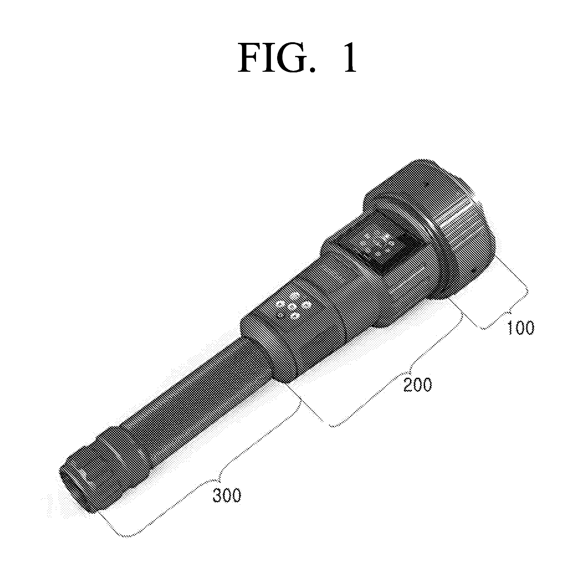
[0060]Referring first to FIGS. 1 to 4, the AV flashlight may mainly include a head portion 100, a body portion 200, and a rear portion 300.

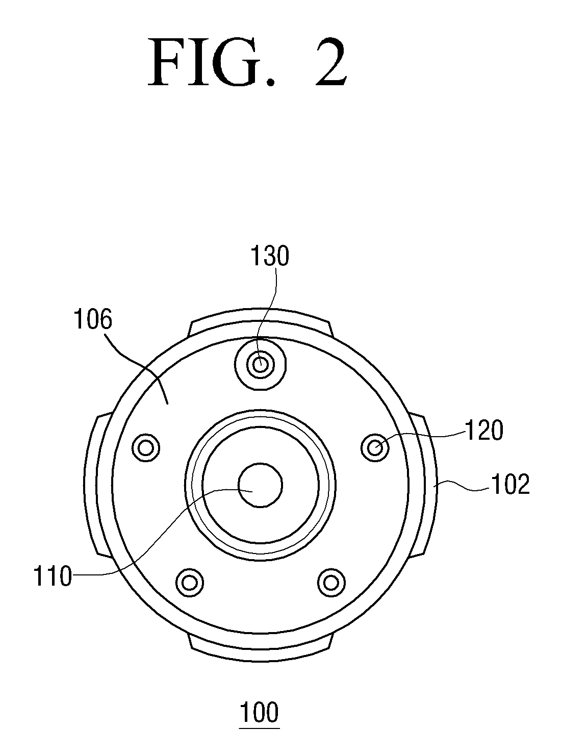
[0061]The head portion 100 may include an O ring 104, a circular light-transmitting plate 106 and a reflective plate 108 mounted on an inner side of a leading end of a head lens barrel 102 which has the largest outer diameter. The circular light-transmitting plate 106 may be made from a high strength transparent glass (e.g., pylex glass) which provides 97% light transmission and 30 m water resistance. A funnel-shaped recess 108a may be extended at a center of the reflective plate 108 in a direction from the front to the back, and a visible light source 110 is engaged with an end of the funnel-shaped recess 108a. An inner inclined surface of the funnel-shaped recess 108a may be treated into a reflective layer to reflect the light emitted from the visible light source 110 in a forward direction. One video camera module mounting hole 108b and four ...

second embodiment

[0127]The structure of the AV flashlight will now be explained with reference to FIGS. 27 to 34.

[0128]First, referring to FIGS. 27 and 28, the AV flashlight according to the second embodiment may mainly include a head portion 1100, a body portion 1200 and a rear portion 1300. The head portion 1100 may include a video camera module 1110, a visible light source module 1120, and an infrared light source module 1130 which are arranged on a front surface. The optical axes of the video camera module 1110 and the visible light source module 1120 are arranged vertically on a vertical bisector of the front surface of the head portion 1100, and three infrared light emitting diodes of the infrared light source module 1130 are arranged on left side and another three infrared light emitting diodes are arranged on right side thereof. The left-side group (LG) of the infrared light emitting diodes are arranged to be inclined so that the diodes are at gradually increasing distance from a left to a ...

third embodiment

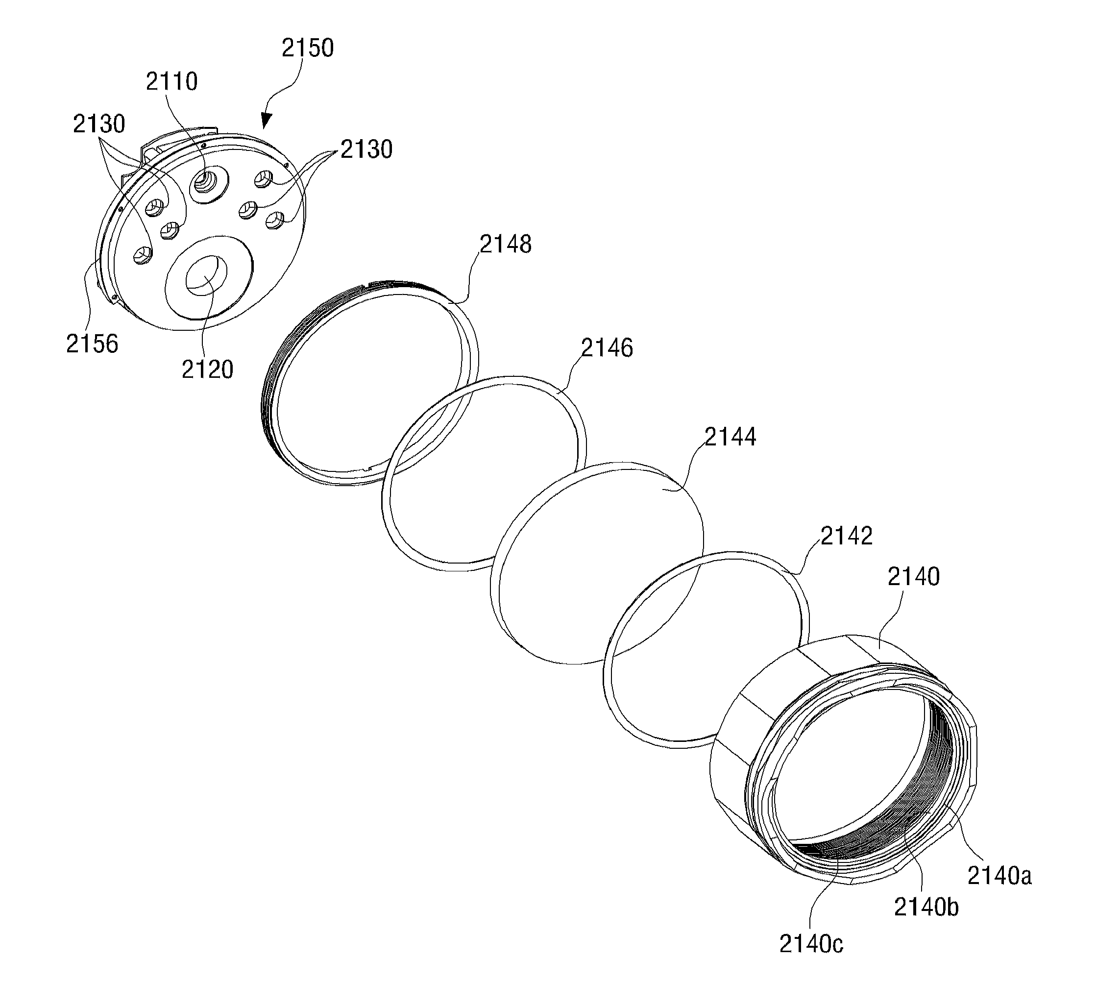
[0175]The structure of an AV flashlight will now be explained with reference to FIGS. 35 to 49.

[0176]Referring to FIGS. 35 and 36, the AV flashlight according to an embodiment may mainly include a head portion 2100, a body portion 2200 and a rear portion 2300.

[0177]The head portion 2100 may include, in order from the left side, a head lens barrel 2140, an O ring 2142, a transparent lens head lens barrel, an annular frame 2146, a fixing annular frame 2148, and a head housing assembly 2150.

[0178]The head lens barrel 2140 has a locking protrusion 2140a formed on a leading end of an inner circumference by aluminum machining. The locking protrusion 2140a has an inner diameter smaller than the outer diameter of the transparent lens head lens barrel. An annular groove 2140b is formed on a rear surface of the locking protrusion 2140a to receive the O ring 2142 therein. A female thread 2140c extends on an inner circumference of the head lens barrel 2140 from the rear surface of the locking ...


PUM


Abstract

An audio and video (AV) flashlight has a head portion, a body portion and a rear portion. Mounted on the head portion is a video camera module incorporating a visible light source and an infrared light source. Mounted on the body portion are a GPS module, an electronic compass module, a display module, a map database module, and a control module to read map information from the map database within a predetermined angle range with reference to an azimuth angle detected through the electronic compass module, display the read information on the display module, and display current location information and current location information of one or more main objects in a forward direction along with linear distance information to the current location. The flashlight enables relative measuring of distance with an eye with respect to a monitoring object based on the linear distance information of the main objects.

Description

CROSS-REFERENCE TO RELATED APPLICATIONS[0001]This application claims priority from Korean Patent Application Nos. 10-2010-0091230, filed on Sep. 16, 2010, 10-2010-0110386, filed on Nov. 8, 2010, and 10-2011-0078233, filed on Aug. 5, 2011, in the Korean Intellectual Property Office, the disclosure of which is incorporated herein by reference in its entirety.BACKGROUND[0002]1. Field of the Invention[0003]The invention relates to a flashlight and a method of displaying map-related video thereof, and more particularly, to a location-based AV flashlight which records geographical location information of the portable flashlight on the move and is capable of video recording, and a method of displaying a map-related video thereof.[0004]2. Description of the Related Art[0005]Flashlights are widely used as emergency lights on sites where lighting is necessary. Developments of high brightness and light efficiency, longer lifespan and low power-consuming LED light source and batteries have furt...

Claims


Application Information

Patent Timeline
IPC IPC(8): H04N7/18
CPCH04N1/00413H04N2201/3253H04N2101/00H04N7/183
Inventor CHOI, SEUNG-LYULSUNG, HYUNG-JA
Owner PHAROBIT
Why Eureka
Try Eureka