
Foreground/Background Separation Using Reference Images

a reference image and background technology, applied in image enhancement, television systems, instruments, etc., can solve the problems of affecting the quality of images, etc., to achieve the effect of spatial economy and performance efficiency

Inactive Publication Date: 2012-03-22
DIGITALPTICS EURO
View PDF4 Cites 24 Cited by
  • Summary
  • Abstract
  • Description
  • Claims
  • Application Information

AI Technical Summary

Benefits of technology

This approach allows for enhanced image processing with improved accuracy and efficiency, reducing computational overhead and enabling real-time correction of defects, such as red-eye and dust artifacts, while optimizing image acquisition parameters without significant delays or loss of image quality.

Problems solved by technology

However, there are situations where flash and non-flash versions of an image may not provide sufficient discrimination, e.g. in bright sunlight.
This represents a substantial additional processing overhead compared to the existing image acquisition process.
Here, the contrast map is specifically built representing substantial additional processing overhead over the existing image acquisition process.
The Epson, Philips and Feng techniques each involve an analysis of only a single image, and do not provide reliable distinctions between foreground and background regions of an image.
Even though human beings have little trouble interpreting images semantically, the challenge to do so using artificial intelligence is not that straight forward.
In a resource-restricted embedded system, such as hand-held image acquisition devices, (e.g., including digital cameras, hand-held computers or cellular phones equipped with a cameras), it is not generally practical to run such a computationally-intensive face detector at real-time frame rates for video.
This allows some level of initial face detection to be achieved, but with undesirably high false positive rates.
In-camera methods, although providing precision, use additional hardware and sometimes movable hardware components which can increase the price of the camera and add a potential maintenance challenge.
However, post-acquisition analysis may not generally provide sufficient precision.
In particular, recognition of inverted faces is known to be a difficult perceptual task.
While the human visual system performs well in recognizing different faces, performing the same task with inverted faces is significantly worse.
The '440 patent also provides no guidance as to how to detect or determine certain features within a scene.
However, these generally only detect motion or abrupt changes in what is generally a stagnant scene.
In general, face detection-based automatic red-eye reduction techniques have high computation and memory resource requirements.
In addition, most of the face detection algorithms are only able to detect faces that are oriented in an upright frontal view.
These approaches generally do not detect faces that are rotated in-plane or out-of-plane with respect to the image plane.
Within an image acquisition subsystem such as is embodied in typical digital cameras, a peak computing load and resource requirements occur around the time of image acquisition.
Such a redeye filter typically compromises its overall performance in terms of accuracy of detection of redeye defects and quality of image correction.
There can be drawbacks to this alternative approach, though.
First, images are displayed on the acquiring device, immediately after acquisition, with uncorrected redeye defects.
Second, when images are accessed in playback mode, there is a further delay while images are post-processed before an image can be displayed.
Both drawbacks would create a negative impression on end users.
Further, as most digital cameras store images using lossy compression techniques there can be additional disadvantages with respect to image quality as images are decompressed and recompressed in order to perform redeye detection and correction processes in playback or background modes.
Such loss of image quality may not become apparent until later when a user wishes to print an image and it is too late to reverse the process.
If redeye processing is delayed until the images are loaded onto another device, such as a desktop PC or printer, there can be further disadvantages.
First, meta-data relating to the acquiring device and its state at the time the image was acquired may not be available to the redeye filter process.
In many cases, knowledge of image characteristics such as image quality may affect the design parameters and decisions the detection and correction software uses.
For example an image with suboptimal exposure may deteriorate the overall detection of red-eye defects.
While working with camera companies, there is a constant complaint about ORBS which are undesirable artefacts in images.

Method used


Image

  • Foreground/Background Separation Using Reference Images
  • Foreground/Background Separation Using Reference Images
  • Foreground/Background Separation Using Reference Images

Examples


third embodiment

[0154]FIG. 5 is an alternative embodiment, wherein the classifiers are rotated as opposed to the images. By doing so, even if the results are similar, the execution time is highly optimized because the process is preferably not repeated over three images, and is instead performed over only a single image with two, three or more times the number of classifiers. Preferably, two sets of rotated classifiers are used along with an unrotated set. According to FIG. 5, the classifiers loaded at block 408 are rotated at block 460 to create counter clockwise classifiers 462, original classifiers 464 and clockwise classifiers 466. As explained above, if desired, a fourth set of classifiers 468 of 180 degree rotation can be generated, and in fact, any number of classifier sets may be generated according to rotations of arbitrary or selected amounts in accordance with alternative embodiments of this invention. In a third embodiment, both the image and the classifiers may be rotated.

[0155]The cla...

embodiment 500

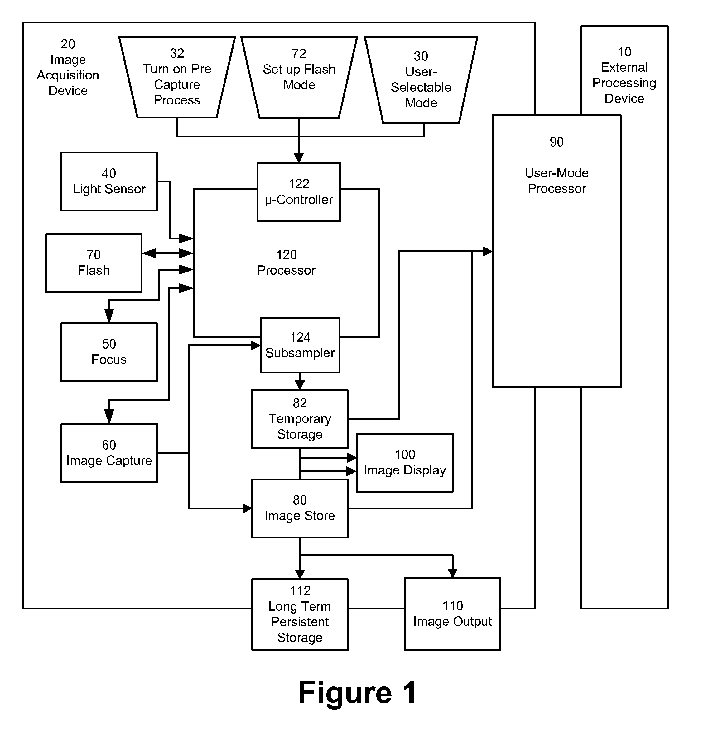
[0168]A description of two different methods of calculating PSF is provided with reference to FIGS. 7a-7b. FIG. 7a shows an embodiment 500 for extracting a PSF using a single preview image. In this embodiment, the input is the finally acquired full resolution image 511, and a saved preview image 512. Prior to creating the PSF, the preview and final image have to be aligned. The alignment can be a global operation, using the entire images, 511 and 512. However, the two images may not be exact for several reasons.

[0169]Due to the fact that the preview image and the final full resolution image differ temporally, there may not be a perfect alignment. In this case, local alignment, based on image features and using techniques known to those skilled in the art, will normally be sufficient. The process of alignment may be performed on selected extracted regions 520, or as a local operation. Moreover, this alignment is only required in the neighborhood of the selected region(s) or feature(s...


PUM


Abstract

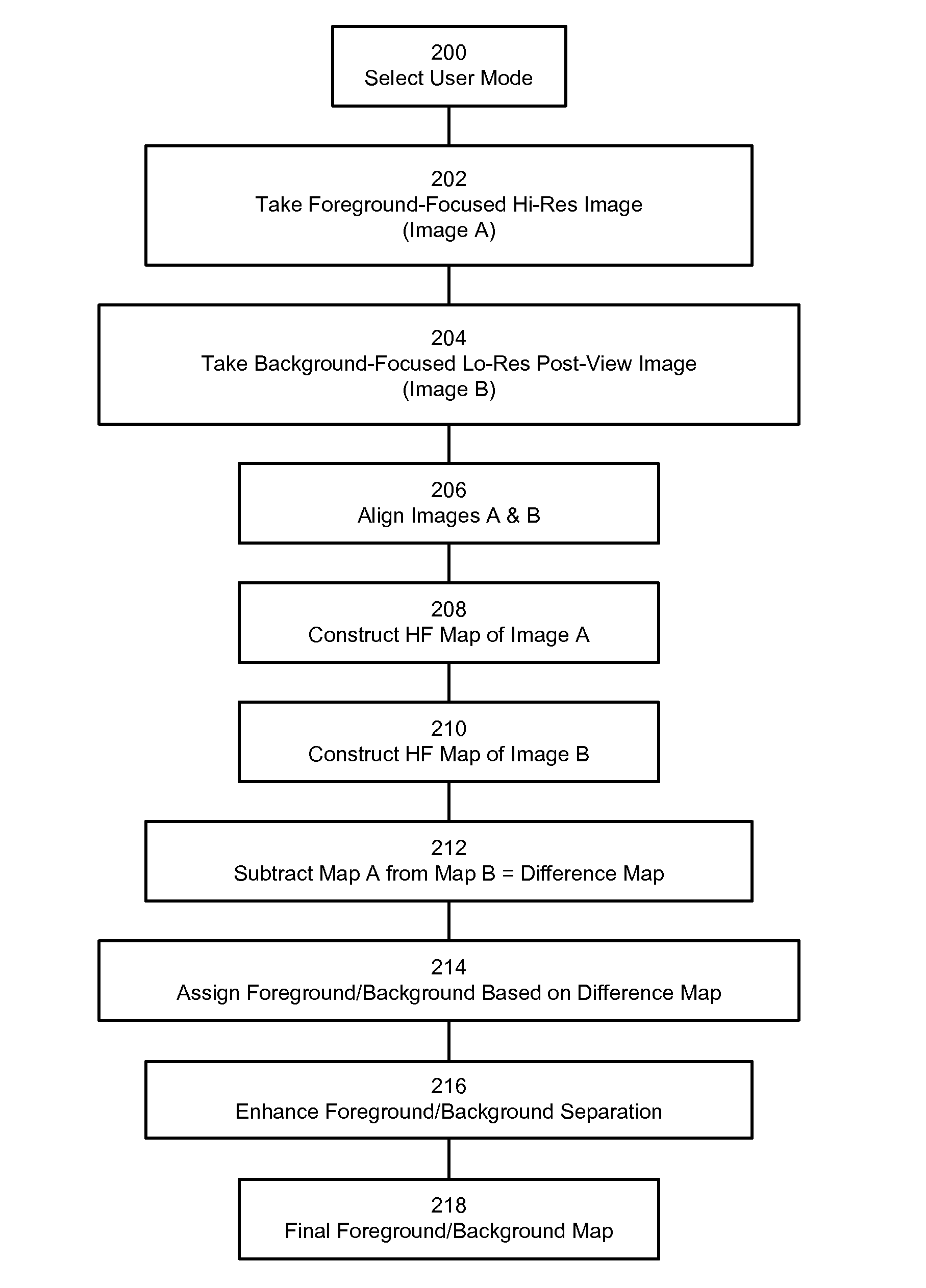
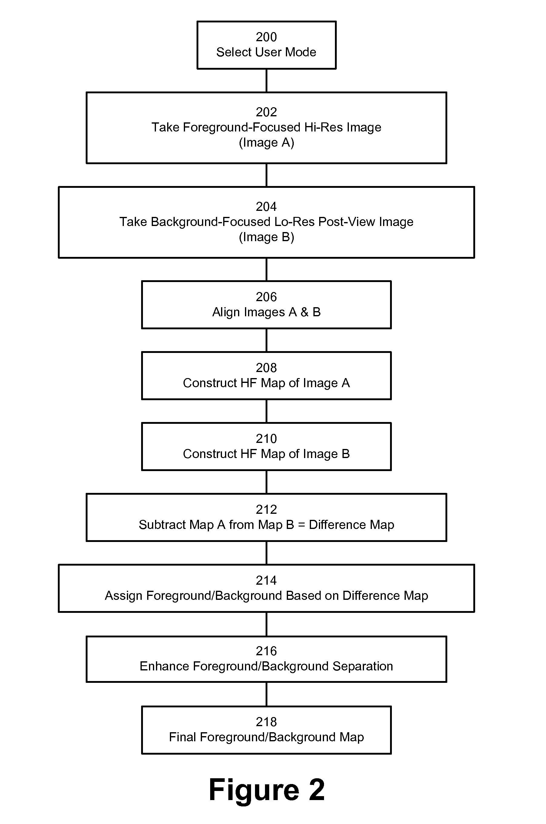
A technique involves distinguishing between foreground and background regions of a digital image of a scene. First and second images are captured of nominally a same scene. The first image is a relatively high resolution image taken with the foreground more in focus than the background, while the second image is a relatively low resolution reference image taken with the background more in focus than the foreground. Regions of the captured images are assigned as foreground or background. In accordance with the assigning, one or more processed images are rendered based on the first image or the second image, or both.

Description

PRIORITY AND RELATED APPLICATIONS[0001]This application is a Division of U.S. patent application Ser. No. 12 / 140,827, filed Jun. 17, 2008; which claims priority to U.S. provisional patent application 60 / 945,558, filed Jun. 21, 2007.[0002]This application is a continuation in part (CIP) of U.S. patent application Ser. No. 11 / 573,713, filed Feb. 14, 2007, now U.S. Pat. No. 7,868,922; which claims priority to U.S. provisional patent application No. 60 / 773,714, filed Feb. 14, 2006, and to PCT application no. PCT / EP2006 / 008229, filed Aug. 15, 2006, published as WO 2007 / 093199.[0003]This application is also a CIP of U.S. patent application Ser. No. 11 / 319,766, filed Dec. 27, 2005, now U.S. Pat. No. 7,692,696.[0004]This application also is related to 11 / 024,046, filed Dec. 27, 2004, now U.S. Pat. No. 7,565,030; which is a CIP of U.S. patent application Ser. No. 10 / 608,772, filed Jun. 26, 2003, now U.S. Pat. No. 7,440,593.[0005]This application also is related to PCT / US2006 / 021393, filed Ju...

Claims


Application Information

Patent Timeline
Patent Type & Authority Applications(United States)
IPC IPC(8): H04N5/262H04N5/225H04N23/40
CPCG06K9/036G06T7/0081H04N5/23219H04N5/222H04N5/2226G06T2207/30196G06T7/11G06V40/161G06V10/993G06V10/242H04N23/611H04N5/262
Inventor STEINBERG, ERANBIGIOI, PETRONELZAMFIR, ADRIANDRIMBAREAN, ALEXANDRUCORCORAN, PETERCIUC, MIHAICAPATA, ADRIAN
Owner DIGITALPTICS EURO
Learn More