Compensating for non-ideal multi-core optical fiber structure

a multi-core, optical fiber technology, applied in the direction of cladded optical fibre, force measurement, instruments, etc., can solve the problems of inability to physically measure variations from ideal fiber structures to this desired degree of accuracy, manufacturing processes are not capable of producing ideal fiber structures, etc., to achieve the effect of accurate determination

Active Publication Date: 2012-03-22
INTUITIVE SURGICAL OPERATIONS INC
View PDF4 Cites 71 Cited by
  • Summary
  • Abstract
  • Description
  • Claims
  • Application Information

AI Technical Summary

Benefits of technology

[0012]Another aspect of the technology relates to an interferometric measurement system that uses compensation parameters previously determined for a spun optical fiber that includes multiple optical waveguides configured in the fiber. The compensation parameters are provided to compensate for variations between an optimal configuration of the multiple optical waveguides in the spun optical fiber and an actual configuration of multiple optical waveguides in the spun optical fiber have been previously determined and preferably stored. Interferometric detection circuitry detects measurement interferometric pattern data associated with each of the multiple optical wavegu...

Problems solved by technology

In performing position measurements of the fiber using this technique, accuracy is limited by how well the strain signals from the independent optical cores can be recombined.
But in practice, manufacturin...

Method used


Image

  • Compensating for non-ideal multi-core optical fiber structure
  • Compensating for non-ideal multi-core optical fiber structure
  • Compensating for non-ideal multi-core optical fiber structure

Examples


Embodiment Construction

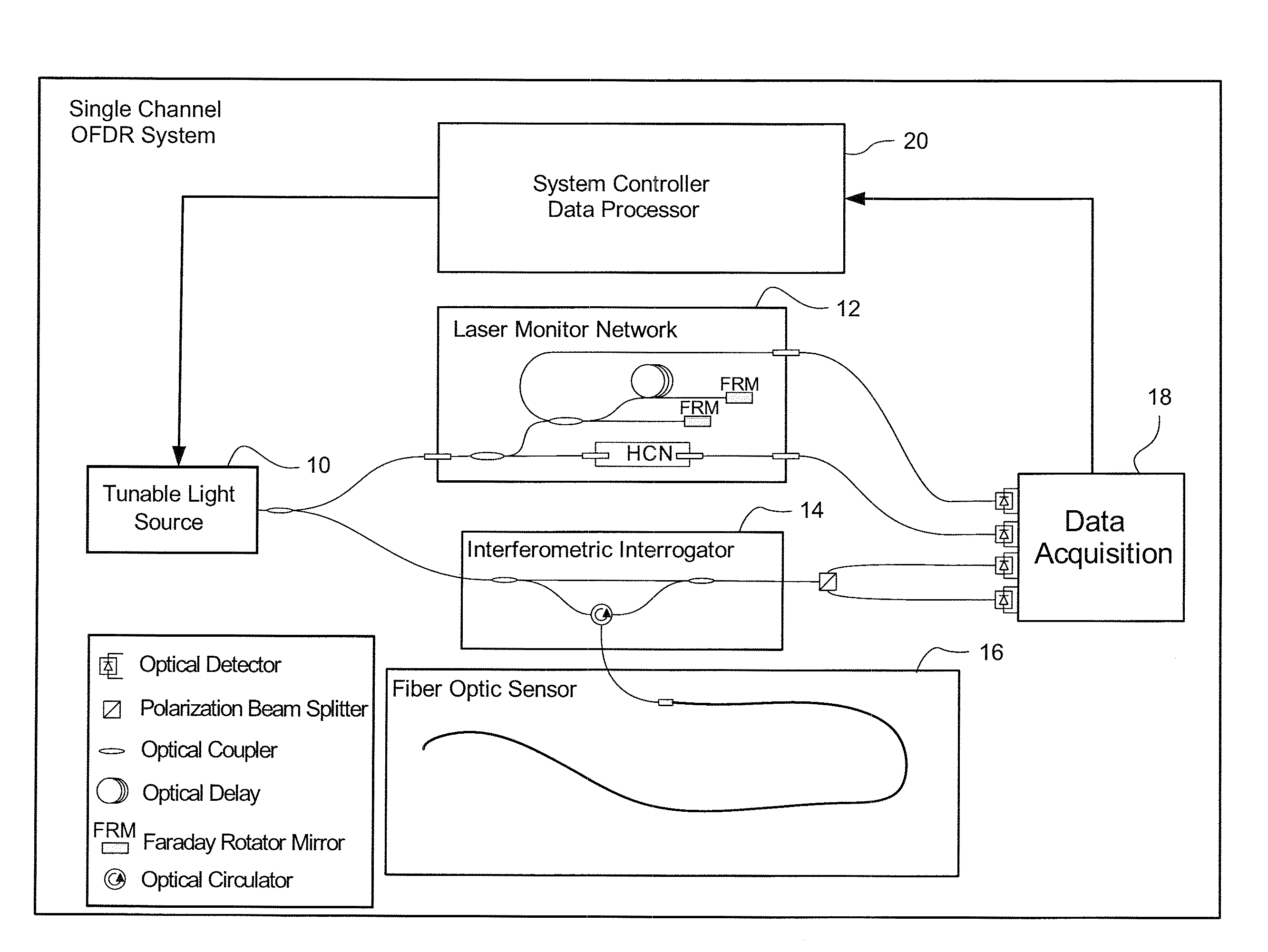
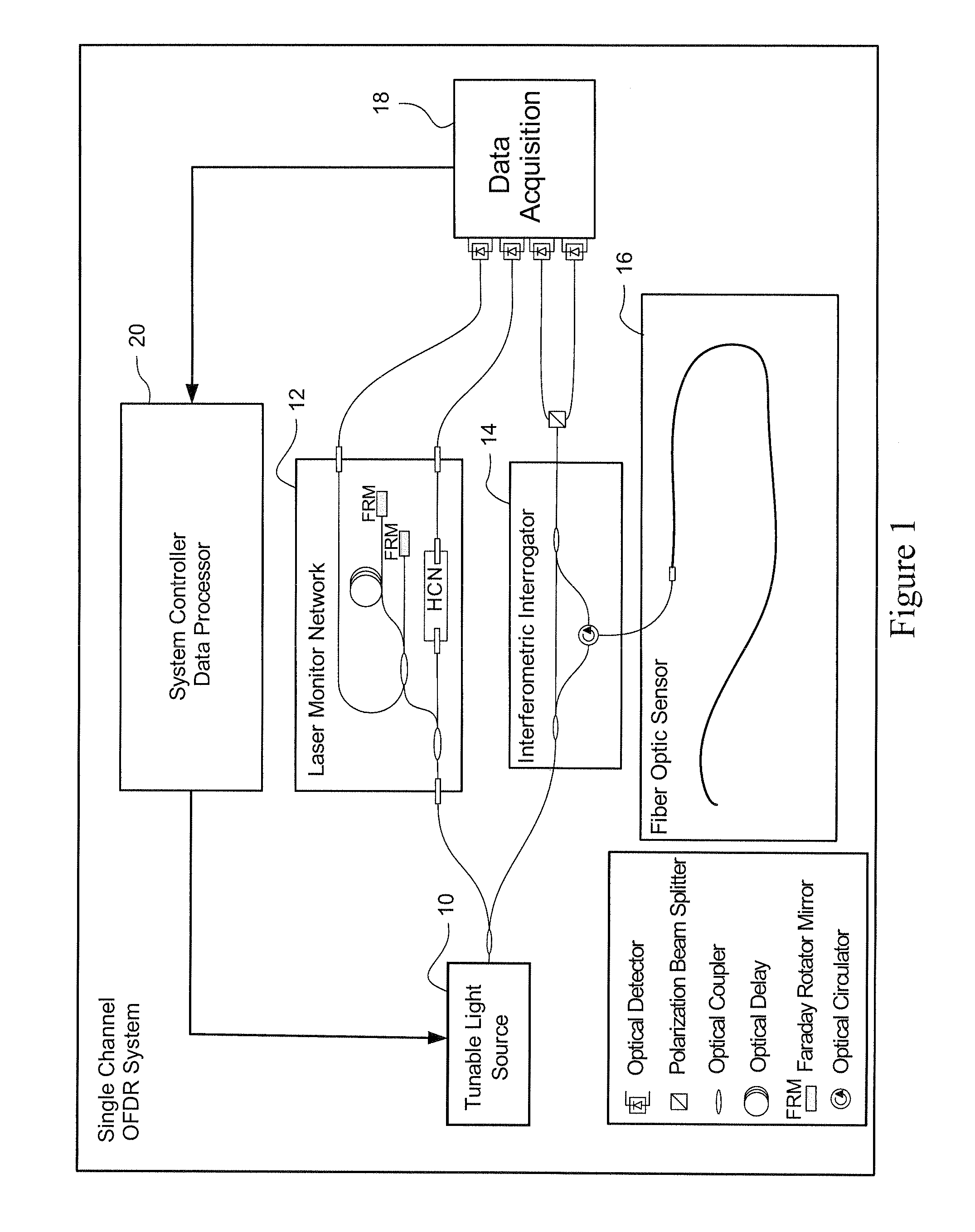
[0037]The following description sets forth specific details, such as particular embodiments for purposes of explanation and not limitation. But it will be appreciated by one skilled in the art that other embodiments may be employed apart from these specific details. In some instances, detailed descriptions of well known methods, interfaces, circuits, and devices are omitted so as not to obscure the description with unnecessary detail. Individual blocks are shown in the figures corresponding to various nodes. Those skilled in the art will appreciate that the functions of those blocks may be implemented using individual hardware circuits, using software programs and data in conjunction with a suitably programmed digital microprocessor or general purpose computer, and / or using applications specific integrated circuitry (ASIC), and / or using one or more digital signal processors (DSPs). Software program instructions and data may be stored on a non-transitory, computer-readable storage me...


PUM


Abstract

An interferometric measurement system includes a spun optical fiber including multiple optical waveguides configured in the fiber. Interferometric detection circuitry detects measurement interferometric pattern data associated with each of the multiple optical waveguides when the optical fiber is placed into a bend. Data processing circuitry determines compensation parameters that compensate for variations between an optimal configuration of the multiple optical waveguides in the fiber and an actual configuration of multiple optical waveguides in the fiber. The compensation parameters are stored in memory for compensating subsequently-obtained measurement interferometric pattern data for the fiber. The compensation parameters are applied to the subsequently-obtained measurement interferometric pattern data in order to distinguish between axial strain, bend strain, and twist strain on the fiber and to accurately determine one or more strain values for the fiber corresponding to one or more of the axial strain, bend strain, or twist strain on the fiber.

Description

PRIORITY APPLICATION[0001]This application claims priority from U.S. provisional patent application Ser. No. 61 / 384,019, filed on Sep. 17, 2010, the contents of which are incorporated herein by reference.TECHNICAL FIELD[0002]The technology relates to interferometric measurements and may be used for example in optical fiber shape and / or position sensing applications.INTRODUCTION[0003]Optical strain sensing is a technology useful for measuring physical deformation of a waveguide caused by, for example, the change in tension, compression, or temperature of an optical fiber. A multi-core optical fiber is composed of several independent waveguides embedded within a single fiber. A continuous measure of strain along the length of a core can be derived by interpreting the optical response of the core using swept wavelength inteferometery. With knowledge of the relative positions of the cores along the length of the fiber, these independent strain signals may be combined to gain a measure o...

Claims


Application Information

Patent Timeline
IPC IPC(8): G01B9/02
CPCG01B11/161G01B9/02023G02B6/02042G01B11/18G01B21/042G01B21/045G01L1/242G01L25/00
Inventor KLEIN, JUSTIN W.FROGGATT, MARK E.KREGER, STEPHEN T.GIFFORD, DAWN K.KLUTE, SANDRA M.
Owner INTUITIVE SURGICAL OPERATIONS INC
Why Eureka
Try Eureka