
Apparatus and method for detectiong cause of radio link failure or handover failure in mobile communication system

a mobile communication system and radio link technology, applied in the field of mobile communication systems, can solve the problems of network still making a wrong determination, cell where the rlf occurs, and cannot differentiate whether, so as to improve the performance of the mobile communication system

Active Publication Date: 2012-03-22
SAMSUNG ELECTRONICS CO LTD
View PDF8 Cites 104 Cited by
  • Summary
  • Abstract
  • Description
  • Claims
  • Application Information

AI Technical Summary

Benefits of technology

The present invention provides a method for detecting the cause of a radio link failure or handover failure in a mobile communication system and optimizing the system accordingly. This is achieved by transmitting an RLF information report to a base station and analyzing the data contained therein to determine the cause of the failure. The method can improve the performance of the mobile communication system and enhance the user experience.

Problems solved by technology

However, after the UE fails in re-establishing the RRC connection (e.g., the eNB receives an RRC re-establishment request but fails during the re-establishment process), if an eNB to which the UE re-establishes the RRC connection transmits a Radio Link Failure (RLF) instruction to an eNB covering a cell where the RLF occurs, the cell where the RLF occurs cannot differentiate whether it is a coverage leak or a too late handover.
If the eNB to which the UE re-establishes the RRC connection does not transmit the RLF instruction to the eNB covering the cell where the RLF occurs, the cell where the RLF occurs can not know the difference between the last successful handover time of the UE and the time that the UE tries to re-establish the RRC connection, and thus can not differentiate whether the handover is too late or too early or is to a wrong cell.
However, even if the UE reports the difference to the network after accessing the network again, the network may still make a wrong determination because the difference between the time that the UE tries to re-establish a RRC connection and the time of the RLF / handover failure is large.
Consequently, the self-optimization process will also be wrong and network performance will be affected.

Method used


Image

  • Apparatus and method for detectiong cause of radio link failure or handover failure in mobile communication system
  • Apparatus and method for detectiong cause of radio link failure or handover failure in mobile communication system
  • Apparatus and method for detectiong cause of radio link failure or handover failure in mobile communication system

Examples


Embodiment Construction

[0029]The following description with reference to the accompanying drawings is provided to assist in a comprehensive understanding of exemplary embodiments of the invention as defined by the claims and their equivalents. It includes various specific details to assist in that understanding but these are to be regarded as merely exemplary. Accordingly, those of ordinary skill in the art will recognize that various changes and modifications of the embodiments described herein can be made without departing from the scope and spirit of the invention. Also, descriptions of well-known functions and constructions are omitted for clarity and conciseness.

[0030]The terms and words used in the following description and claims are not limited to the bibliographical meanings, but are merely used by the inventor to enable a clear and consistent understanding of the invention. Accordingly, it should be apparent to those skilled in the art that the following description of exemplary embodiments of t...


PUM


Abstract

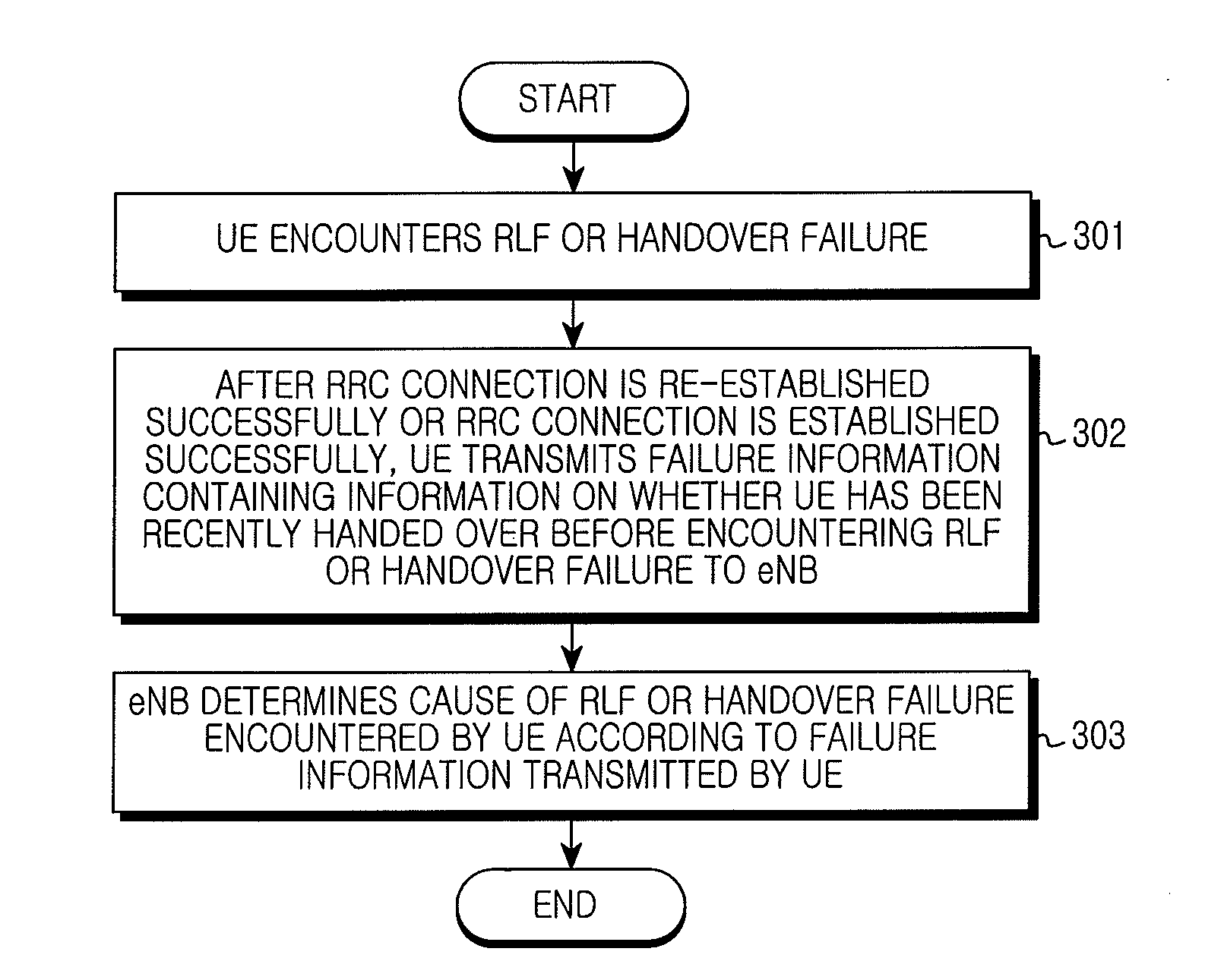
A terminal, a Base Station (BS) and a method for detecting a cause of a Radio Link Failure (RLF) or handover failure are provided. The method includes determining whether an RLF or a handover failure occurs, performing a process of a connection re-establishment or connection establishment to enter a connection mode after encountering the RLF or the handover failure, and transmitting an RLF information report to a BS after entering the connection mode.

Description

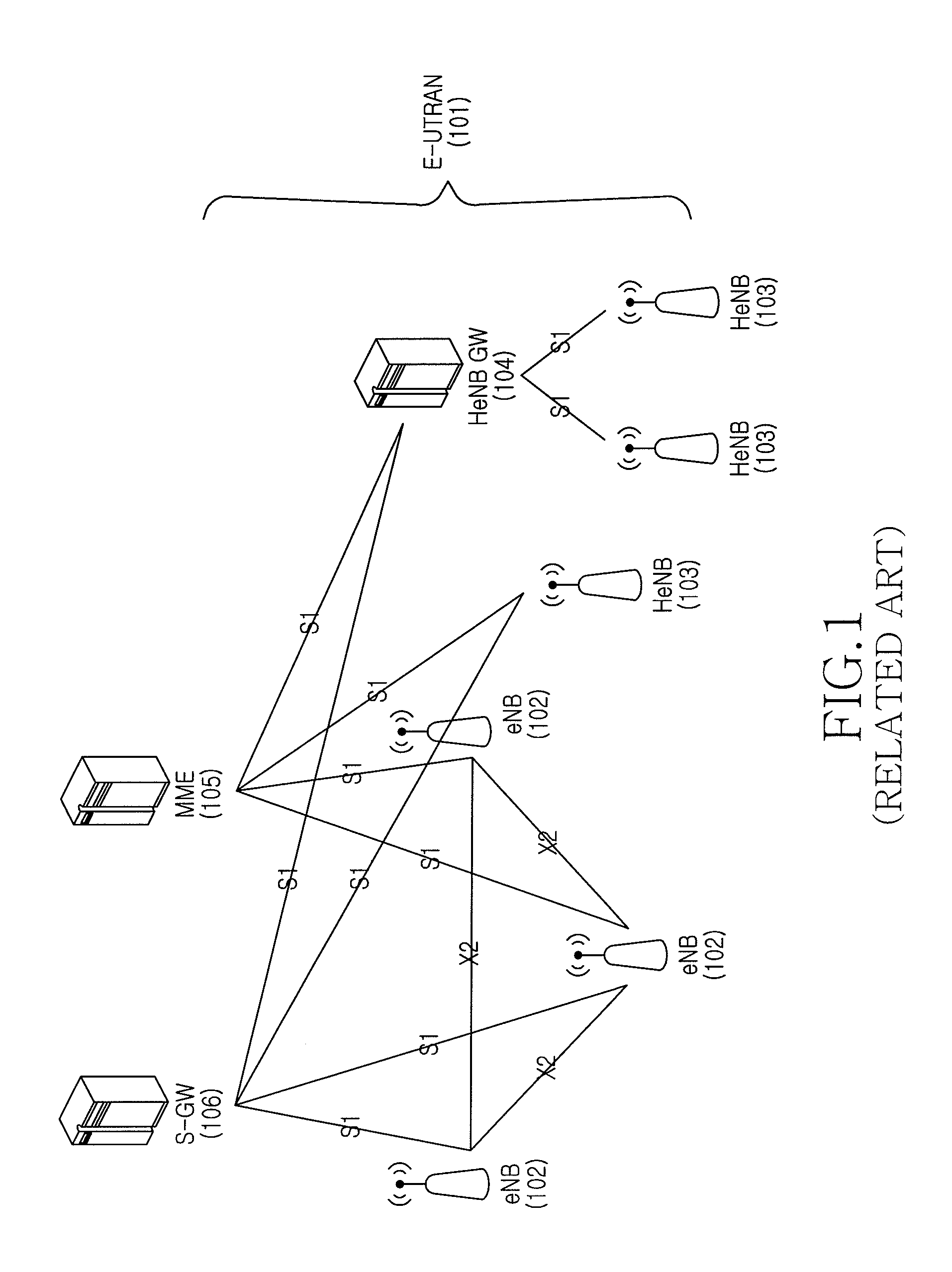
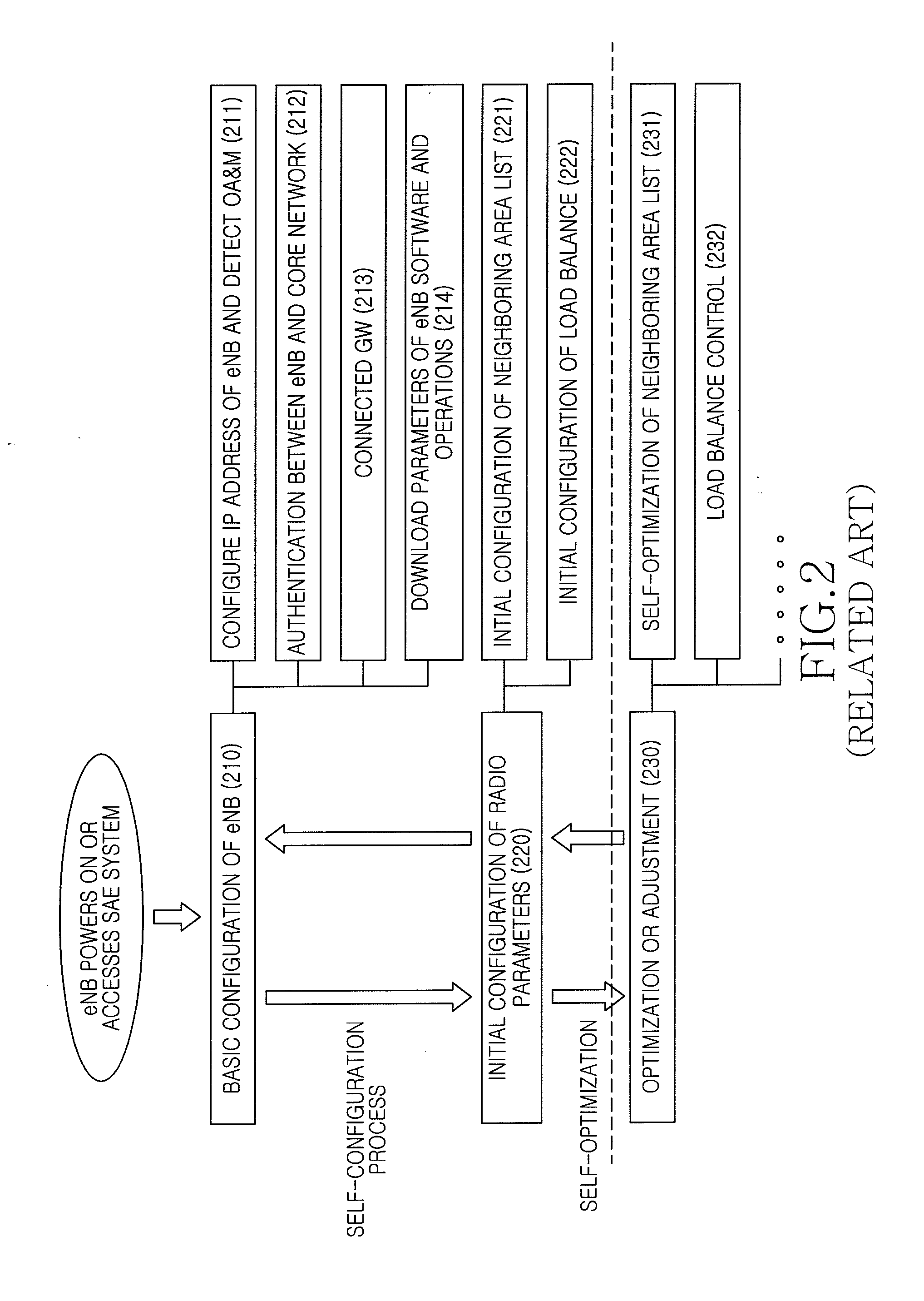
PRIORITY[0001]This application claims the benefit under 35 U.S.C. §119(a) of a Chinese patent application filed in the Chinese Intellectual Property Office on Sep. 21, 2010 and assigned Serial No. 201010292445.3, the entire disclosure of which is hereby incorporated by reference.BACKGROUND OF THE INVENTION[0002]1. Field of the Invention[0003]The present invention relates to the field of mobile communication systems. More particularly, the present invention relates to a method for detecting the cause of a Radio Link Failure (RLF) or handover failure in mobile communication systems.[0004]2. Description of the Related Art[0005]Along with the development of communication technologies, the mobile communication system has evolved into a System Architecture Evolution (SAE) system. FIG. 1 is a schematic diagram illustrating a structure of the SAE system according to the related art. Referring to FIG. 1, the SAE system includes an Evolved Universal Terrestrial Radio Access Network (E-UTRAN) ...

Claims


Application Information

Patent Timeline
Patent Type & Authority Applications(United States)
IPC IPC(8): H04W24/00H04W36/00H04L12/26
CPCH04W24/00H04W76/027H04W36/00H04W76/18H04W76/38H04W76/19H04W36/0058H04W36/0079H04L41/0654H04W88/08
Inventor XU, LIXIANGVAN LIESHOUT, GERT-JANVAN DER VELDE, HIMKE
Owner SAMSUNG ELECTRONICS CO LTD
Learn More