
Telecommunication quality measurement system adapted for sharing test equipment between operators

a technology of telecommunication quality and test equipment, applied in the field of telecommunication quality measurement system, can solve problems such as incorrect call charging, voice or video quality in voice-oriented networks may be inferior, and the network performs not to acceptable standards

Inactive Publication Date: 2012-03-22
LAGER PETER
View PDF5 Cites 11 Cited by
  • Summary
  • Abstract
  • Description
  • Claims
  • Application Information

AI Technical Summary

Benefits of technology

[0057]Through the invention, authentication of TCS servers is enforced so that only authorized users gain access to test-call results from terminating dialers. Furthermore,

Problems solved by technology

Occasionally, these networks do not perform to acceptable standards.
For example, voice or video quality in a voice-oriented network may be inferior, or a network signals false answer.
False answer is when a network of a called party replies to a network of a calling party that the called party has seized the call although it has not, resulting in incorrect call-charging.
Occasionally though, CLI-forwarding fails.
Thereby, problems with CLI may be localized to a specific network or operator by altering the routes.
A problem in the art is that assessment of voice quality in a TCS server is restricted to one direction because there is no appropriate network channel for sending voice clips from a terminating dialer to a TCS server.
Another problem in the art relates to CLI-forwarding.
Yet another problem is related to pooling.
Busy-calls are a waste of dialer capacity.
There is another problem relating to cost.
Yet another problem is that the dialers are susceptible to unauthorized usage.
Unauthorized usage consumes capacity from a potentially scarce resource, among other things.

Method used


Image

  • Telecommunication quality measurement system adapted for sharing test equipment between operators
  • Telecommunication quality measurement system adapted for sharing test equipment between operators
  • Telecommunication quality measurement system adapted for sharing test equipment between operators

Examples


Embodiment Construction

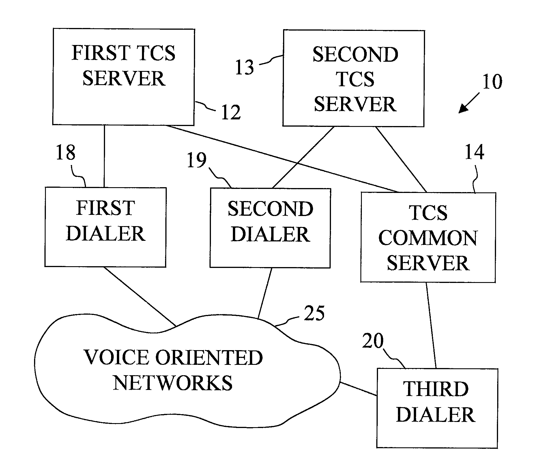
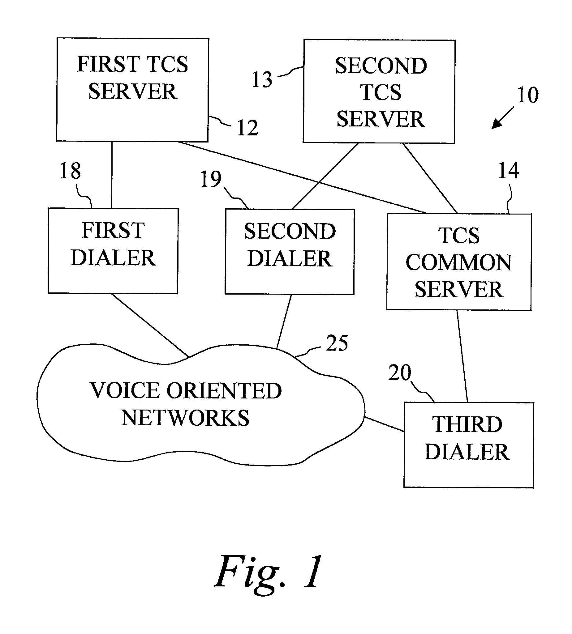
[0063]The invention will now be described in more detail. In FIG. 1 there is shown a telecommunications quality measurement system 10 in accordance with the invention. In the forthcoming, it will be called “Test-Call System” (TCS).

[0064]The TCS 10 comprises a first TCS server 12, a second TCS server 13, a TCS common server 14, a first dialer 18, a second dialer 19 and a third dialer 20. The first dialer 18 and the second dialer 19 are originating dialers, while the third dialer 20 is a terminating dialer.

[0065]They are interconnected for facilitating data communication through TCP / IP as shown. Accordingly, the first TCS server 12, the second TCS server 13 and the third dialer 20 are connected to the TCS common server 14 for facilitating data communication. Moreover, the first dialer 18 is connected to the first TCS server 12, and the second dialer 19 is connected to the second TCS server 13 for facilitating data communication.

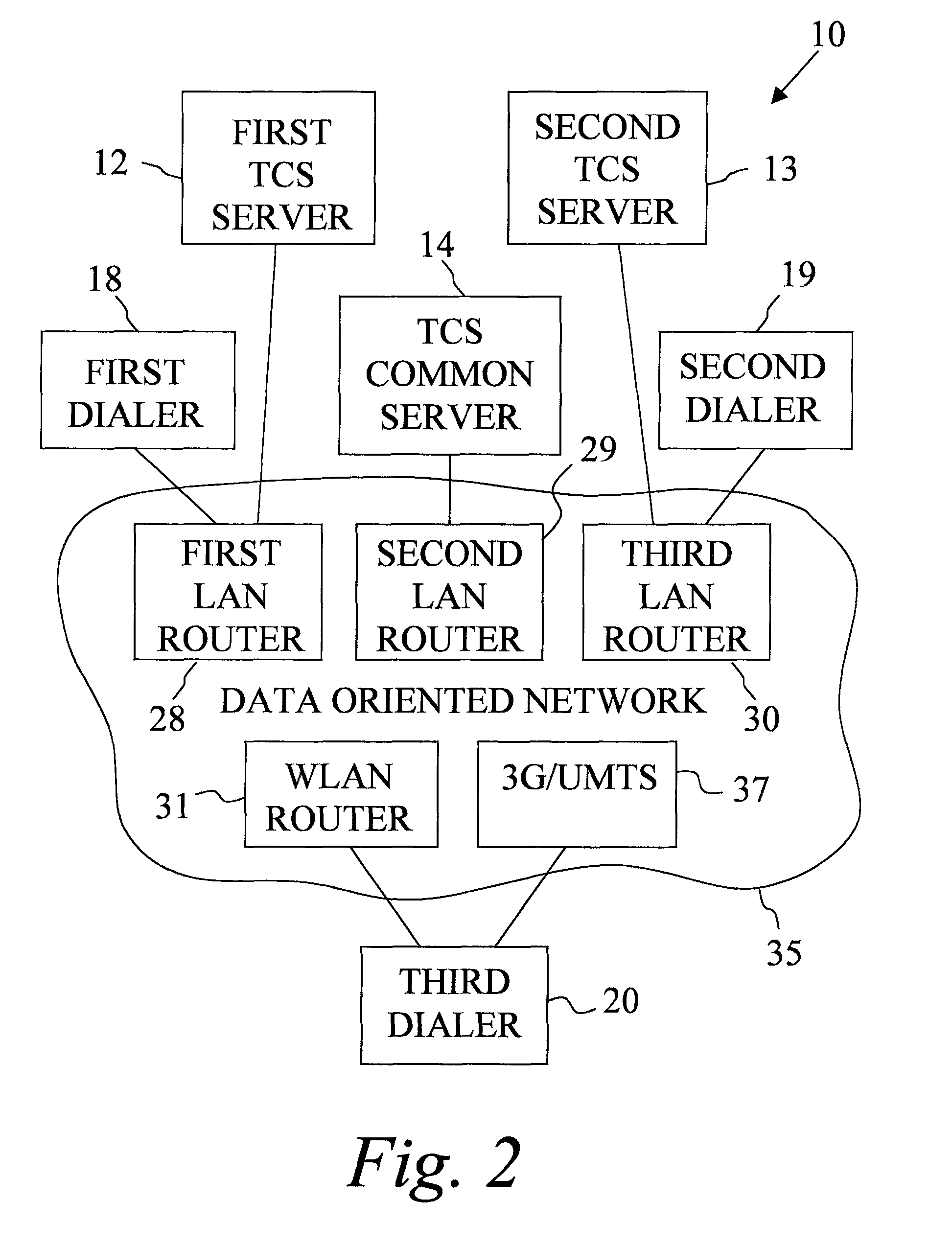
[0066]The first dialer 18, the second dialer 19, and the ...


PUM


Abstract

A telecommunications quality measurement system has dialers that initiate and receive telephonic test-calls through voice-oriented networks under the control and supervision of test-call-system servers. A test-call-system common server comprises a locking and queuing device that queues lock queries from test-call-system servers. Locks prevent concurrent test-calls to parties of terminating dialers. The test-call-system servers are granted permission to command initiation of test calls, one at the time in a first-come-first-serve manner to a specific party. The test-call-system common server and the terminating dialers are connected to a data-oriented network for facilitating data communication between them. Results from the test calls are sent from the terminating dialers to the appropriate test-call-system servers via the test-call-system common server.

Description

TECHNICAL AREA[0001]The present invention relates to telecommunications. More specifically, the invention relates to a system for telecommunications quality measurements.BACKGROUND ART[0002]For facilitating telecommunications in the world, there is employed a global telecommunications interconnection network. It comprises traditional fixed Public Switched Telephony Networks (PSTN) to which e.g. Plain Old Telephone Service (POTS) terminals are connected. It furthermore comprises a diversity of networks that employ other technologies, to cater for other telecommunication services and other types of terminals.[0003]A traditional PSTN is based on circuit switching. It is a technology well adapted for POTS because of its real-time characteristics. At the advent of data communication, modems were introduced for sending data through PSTNs. However, packet switched networks emerged because of their superior efficiency for data communication. The Internet is an example of a network that uses...

Claims


Application Information

Patent Timeline
IPC IPC(8): H04M1/24H04L43/50
CPCH04L12/2697H04W24/08H04M3/2236H04L43/50
Inventor LAGER, PETER
Owner LAGER PETER
Learn More