Image forming system and control apparatus

a technology of image forming and control apparatus, applied in the direction of electrographic process apparatus, instruments, optics, etc., can solve the problems of large output, continuous operation, and stoppage of image forming operation, and achieve the effect of properly executing productivity recovery and smooth recovery of original connected

Inactive Publication Date: 2012-03-22
CANON KK
View PDF3 Cites 7 Cited by
  • Summary
  • Abstract
  • Description
  • Claims
  • Application Information

AI Technical Summary

Benefits of technology

[0010]The present invention proposes a control method for causing a connected image forming apparatus to smoothly recover an original connected image forming state from a state in which one image forming apparatus cannot perform image forming and the other image forming apparatus continues image forming. By applying the control method of the present invention, it is possible to properly execute productivity recovery.

Problems solved by technology

In addition to a toner shortage state, when printing materials run out, an image forming operation stops.
In such a market, a large amount of output and continuous operation is needed.

Method used


Image

  • Image forming system and control apparatus
  • Image forming system and control apparatus
  • Image forming system and control apparatus

Examples


first embodiment

[0036][Overview of Connected Image Forming Apparatus]

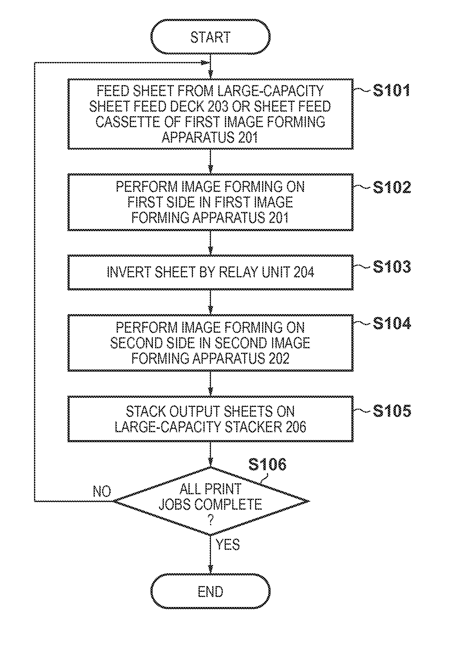
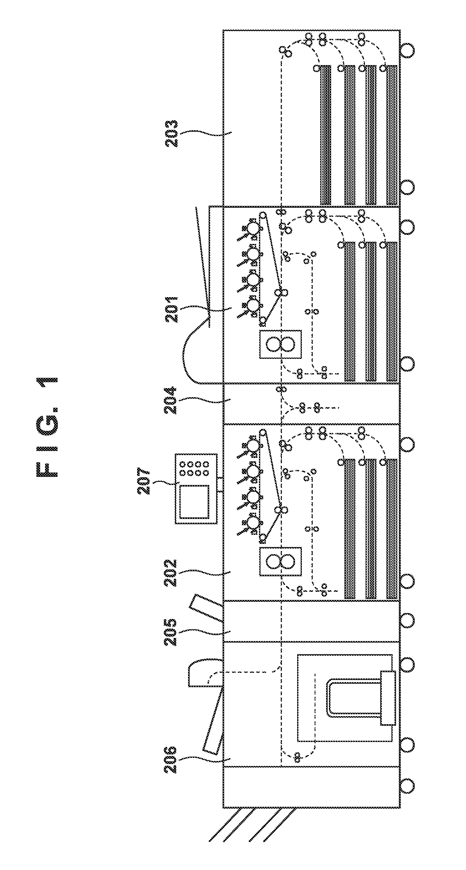
[0037]FIG. 1 is a view showing the schematic configuration of a connected image forming apparatus serving as an image forming system according to this embodiment. A first image forming apparatus 201 and a second image forming apparatus 202 which are the same type, and a relay unit 204 constitute an image forming section. That is, two image forming apparatuses are included in this embodiment. A large-capacity sheet feed deck 203 capable of accommodating a large number of printing sheets is arranged upstream of the image forming section. On the other hand, an inserter 205 is arranged downstream of the image forming section, and a large-capacity stacker 206 is also arranged downstream of the inserter 205. There is provided, on the second image forming apparatus 202, an external display device 207 for executing an image forming operation.

[0038]The large-capacity sheet feed deck 203 can accommodate sheets the number of which is larger ...

second embodiment

[0180]In the first embodiment, connected operation recovery control when a connected double-sided operation is recovered from a state in which the first image forming apparatus has stopped and the second image forming apparatus is performing a double-sided printing operation has been described. In this embodiment, connected operation recovery control when a connected double-sided operation is recovered from a state in which the second image forming apparatus has stopped and the first image forming apparatus is performing a double-sided printing operation will be explained.

[0181]The configuration of the connected image forming apparatus of this embodiment is the same as in the first embodiment, and a repetitive explanation will be omitted. Only characteristic part of the connected operation recovery control in this embodiment will be explained in detail.

[0182][Recovery Control when First Image Forming Apparatus can Perform Double-Sided Printing Operation and Second Image Forming Appa...


PUM


Abstract

A control apparatus controls at least one of the first image forming apparatus and the second image forming apparatus connected downstream of the first image forming apparatus so that when switching from a first mode to a second mode, if the second image forming apparatus is unable to perform image forming on a second side of a sheet whose first side has undergone image forming in the second image forming apparatus before the second image forming apparatus performs image forming on a second side of a sheet whose first side has undergone image forming in the first image forming apparatus, an order of the sheet whose first and second sides undergo image forming in the second image forming apparatus and the sheet whose first side undergoes image forming in the first image forming apparatus and whose second side undergoes image forming in the second image forming apparatus is not swapped.

Description

BACKGROUND OF THE INVENTION[0001]1. Field of the Invention[0002]The present invention relates to a connected image forming system for performing image forming by connecting a plurality of image forming apparatuses.[0003]2. Description of the Related Art[0004]In recent years, demands for high speed, high image quality, color print, low energy consumption, and the like have become increasingly high for image forming apparatuses such as copying machines, printers, and multifunctional peripherals. For such electrophotographic image forming apparatuses, a tandem image forming apparatus has been proposed in which relay units that convey a printing material are provided between a plurality of image forming apparatuses to perform image forming. In this type of image forming apparatuses, each apparatus has charging, exposure, developing, transfer, and fixing devices. A first image forming apparatus forms an image on one side (first side) of a printing material, and inverts the printing mater...

Claims


Application Information

Patent Timeline
Patent Type & Authority Applications(United States)
IPC IPC(8): G03G15/00
CPCG03G2215/00021G03G15/231
Inventor NOSE, KATSUYA
Owner CANON KK
Why Eureka
Try Eureka