Controlled negative pressure apparatus and absorbency mechanism
a negative pressure apparatus and negative pressure technology, applied in the direction of suction pumps, dressings, other medical devices, etc., can solve the problem of limiting patient mobility
- Summary
- Abstract
- Description
- Claims
- Application Information
AI Technical Summary
Benefits of technology
Problems solved by technology
Method used
Image
Examples
example 1
Reduced Variation in Pressure with High Viscosity Lubricant
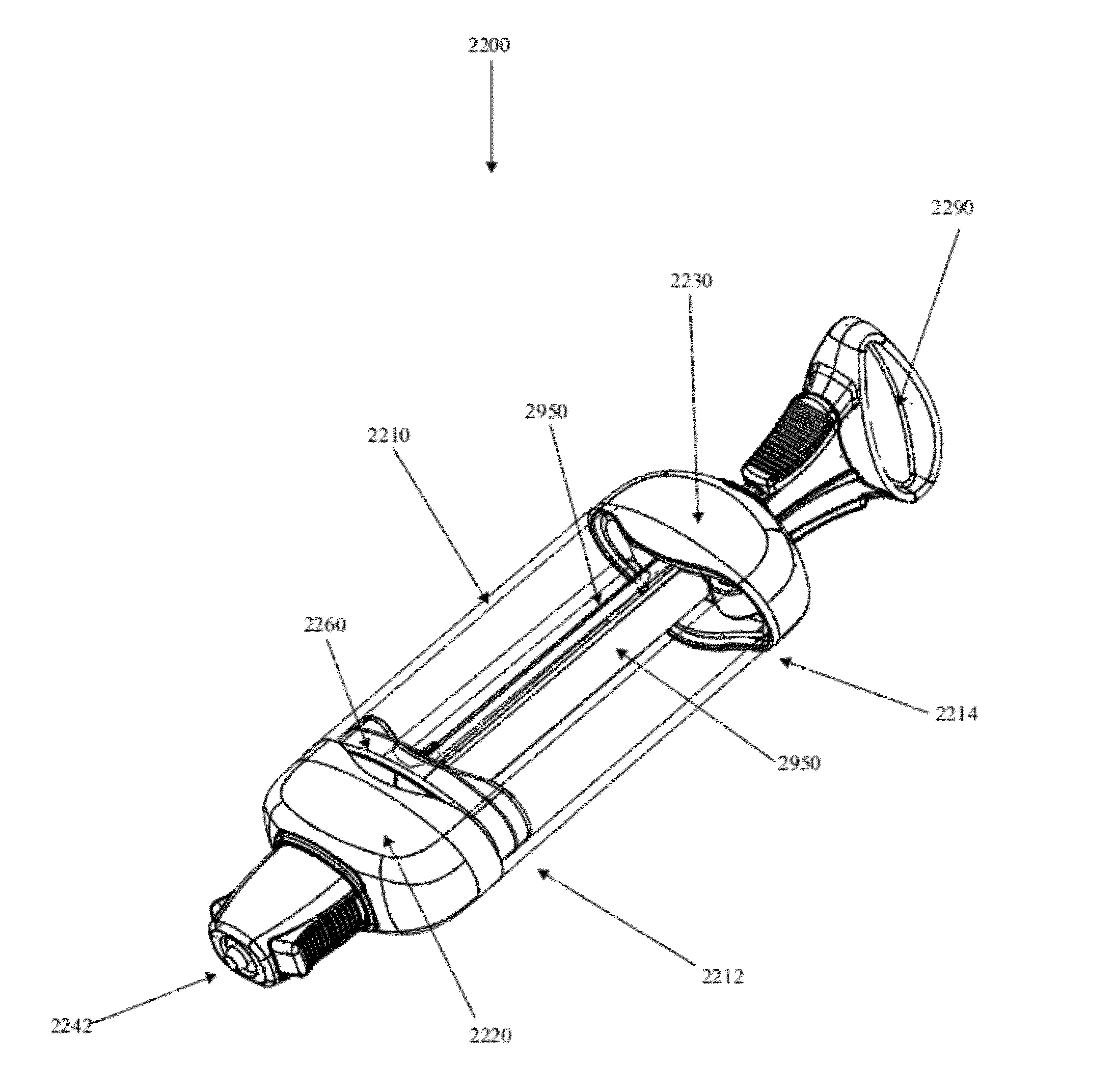
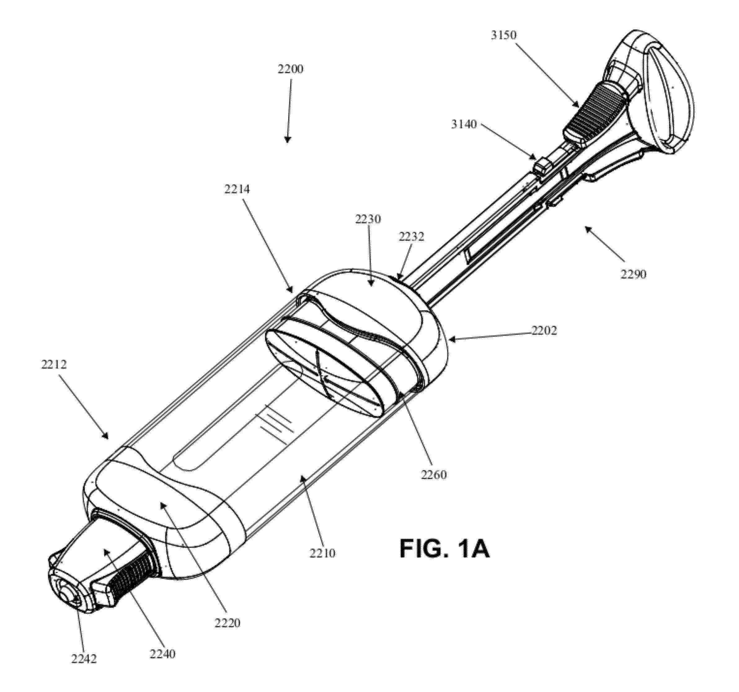
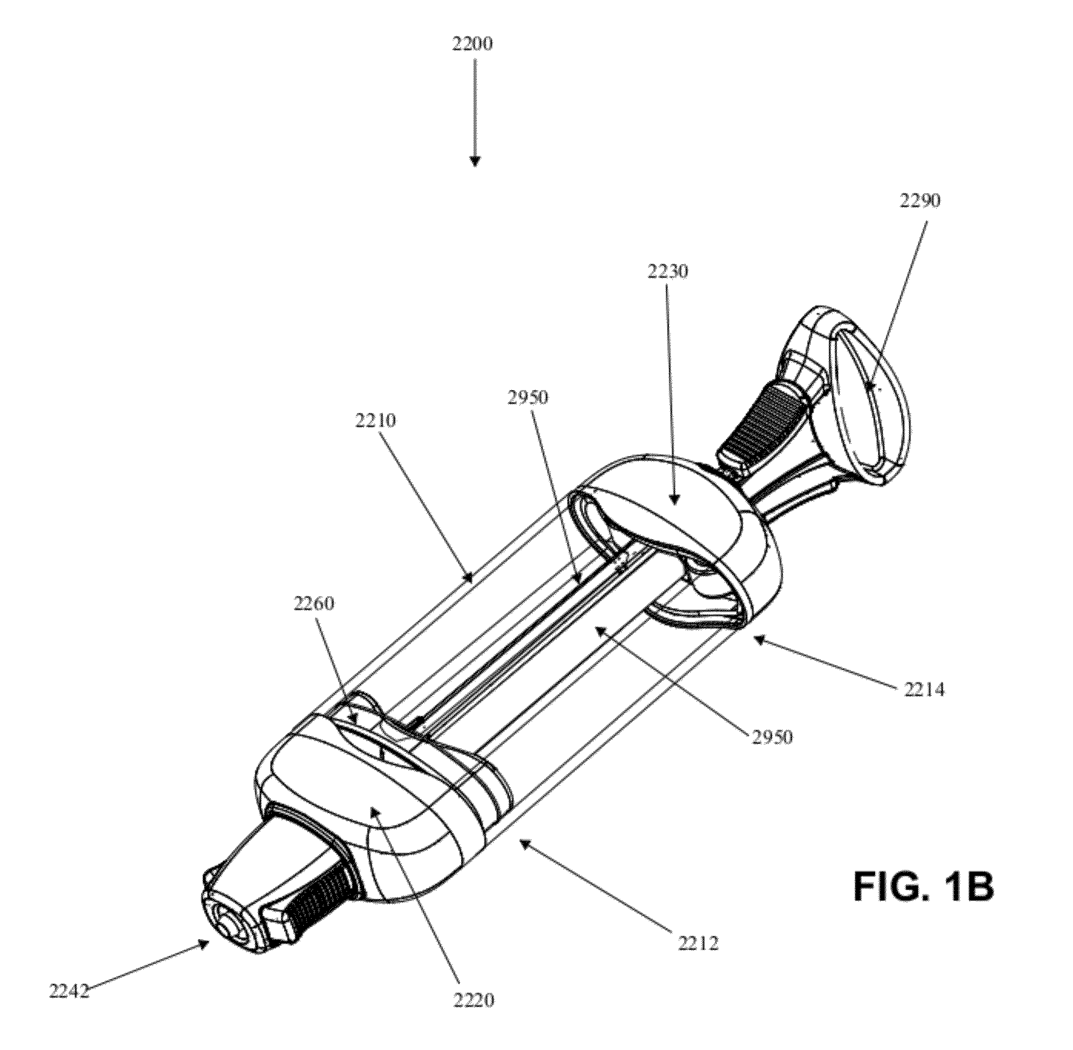
[0167]In this example, the use of a high-viscosity liquid lubricant is shown to reduce pressure fluctuations in the suction device with a simulated leak.
[0168]Cartridge A: A suction device (SNaP suction device), wherein a non-optimized lubricant (fluorosilicone; 100,000 cP) was used to reduce friction between the seal and inner surface of the suction chamber was primed. A simulated air leak of 3 cc / hour was introduced into the apparatus. A total of 50 cc of air was allowed into the suction chamber over a period of about 16.7 hours. The pressure was measured over the duration of the experiment.
[0169]Cartridge B: The same conditions described above were applied to a different suction device, wherein a lubricant of a higher viscosity (20:80 fluorosilicone / dimethylsilicone, 1,500,000 cP) was employed.
[0170]FIGS. 21 and 22 show the plots of the pressure over time for each of the apparatuses, respectively.
[0171]The pressure variat...
example 2
Seal to Seal Mount Configuration
[0172]This example provides a description of a free-floating sliding seal that can accommodate radial compression from narrowing of the inner diameter of the chamber. FIG. 23 is a cross-sectional view of a seal assembly positioned within the suction chamber. The elastomer seal is supported by a seal mount. A gap exists between the portion of the seal closer to the chamber wall and structures of the seal mount. As the inner dimensions of the chamber narrows, the walls of the chamber applies a force to the contact areas of the sliding seal, which in turn are displaced into the small gap. The gap, therefore, absorbs deformation of the sliding seal and any increase in frictional resistance between the seal lips and the chamber wall is reduced. If instead the design incorporated a line-to-line fit between the sliding seal inner surface and seal mount, upon narrowing of the chamber, the seal lips would exert a force against the chamber wall and the friction...
example 3
Modified Bushing-Spring Assembly
[0173]This example describes a modified bushing design which reduces rotational resistance variations in the spring.
[0174]Another factor which hinders the ability to deliver constant pressure throughout the length of the seal travel relates to the construction of the springs. Ribbon springs are constructed from thin strips of metal, such as 301 Stainless steel, which are coiled tightly. The springs extend by unwinding, and as they are unwound, their coiled state provides resistance. Because the local geometry at the point of unwinding remains relatively unchanged regardless of the length of spring that has been unwound, the resistance, and therefore force, remains constant. If, on the other hand, the local geometry was disturbed, the resistance of the spring and subsequently the force it exerts changes.
[0175]Because of the coiled construction of the ribbon spring, there will always be one end of the spring which will be present on the inside diameter ...
PUM
 Abstract
Description
Claims
Application Information
 - R&D
- Intellectual Property
- Life Sciences
- Materials
- Tech Scout
- Unparalleled Data Quality
- Higher Quality Content
- 60% Fewer Hallucinations
Browse by: Latest US Patents, China's latest patents, Technical Efficacy Thesaurus, Application Domain, Technology Topic, Popular Technical Reports.
© 2025 PatSnap. All rights reserved.Legal|Privacy policy|Modern Slavery Act Transparency Statement|Sitemap|About US| Contact US: help@patsnap.com


