Method For Determining Gas Concentrations in a Gas Mixture Based on Thermal Conductivity Measurements With Correction of Measured Values

a technology of thermal conductivity and gas mixture, which is applied in the direction of material thermal conductivity, material thermal analysis, instruments, etc., can solve the problems of insufficient for a more precise determination of the composition of gas mixtures, above the approximate formula, etc., and achieve the effect of improving the measurement precision

Inactive Publication Date: 2012-03-29
THERMO ELECTRONICS LED GMBH
View PDF10 Cites 14 Cited by
  • Summary
  • Abstract
  • Description
  • Claims
  • Application Information

AI Technical Summary

Benefits of technology

[0009]It is the object of the present invention to provide an alternative or improved method for determining gas concentrations in a gas mixture using a thermal conductivity detector with a Wheatstone bridge. In particular, the method shall provide improved measuring precision.
[0016]According to a preferred embodiment of the present invention, a change in temperature for determining at least one additional measured value for the thermal conductivity at another temperature occurs by impressing a defined current pulse on the direct current. The total current intensity resulting from the impressed current pulse can be either increased or reduced in comparison with the initial intensity of the direct current applied standardly. If the total current intensity is increased by impressing the current pulse, this leads to an increase in the temperature in the heating wires of the gas chambers, thus enabling a thermal conductivity measurement at higher temperatures. If, on the other hand, a current pulse is impressed on the operating direct current that reduces the total current intensity, then the temperature of the heating wires is decreased and the thermal conductivity of the gas mixture can be determined at this lower temperature.
[0019]According to a further preferred embodiment of the present invention, a resistor with a known value is connected to a branch of the Wheatstone bridge for the measured value correction, and the bridge voltage is measured with the connected resistor. The connected resistor can be a single resistor or a network of resistors. The important thing is that the magnitude of this resistor is precisely known. Preferably, the connection of the known resistor occurs only after the impression of a negative pulse on the direct current, the intensity of which is calculated in such a way that the value zero results from the theoretically expected bridge voltage. Such a pulse is, e.g., described above with regard to the zero-point correction. The bridge voltage measured thereafter with the connected resistor then depends on the magnitude of the connected resistor alone. This allows a simple and precise calculation of the theoretically expected value for the bridge voltage, which can be compared with the actually measured bridge voltage. If there is a deviation between the measured value for this bridge voltage and the theoretically precisely known value, this deviation is determined and used for self-correction. In the simplest case, this deviation can be added as an offset value to the measured bridge signals.
[0024]According to a preferred embodiment of the present invention, at least one concentration xi of a substance in the gas mixture is displayed. Such a display, e.g., on a monitor or a simple display, allows continuous monitoring of the material concentration of interest by personnel.
[0026]In accordance with a preferred embodiment of the present invention, the program code contains an algorithm for zero-point correction and / or an algorithm for measuring range correction. This allows a particularly fast correction of measured values for the bridge voltage; as a result, gas concentrations of the gas mixture can be determined especially quickly and precisely.

Problems solved by technology

In this respect, xi designates the mol fraction of the gas i. The above approximate formula is, however, insufficient for a more precise determination of the composition of gas mixtures.

Method used


Image

  • Method For Determining Gas Concentrations in a Gas Mixture Based on Thermal Conductivity Measurements With Correction of Measured Values
  • Method For Determining Gas Concentrations in a Gas Mixture Based on Thermal Conductivity Measurements With Correction of Measured Values
  • Method For Determining Gas Concentrations in a Gas Mixture Based on Thermal Conductivity Measurements With Correction of Measured Values

Examples


Embodiment Construction

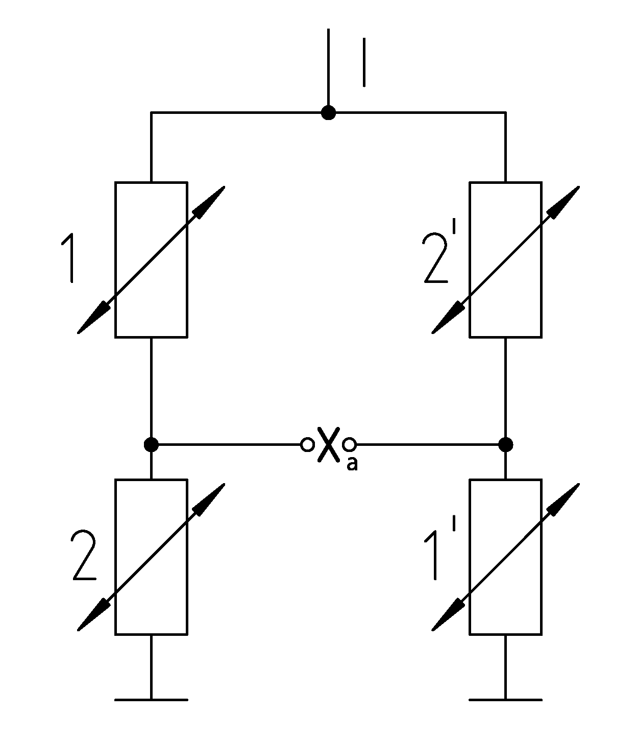
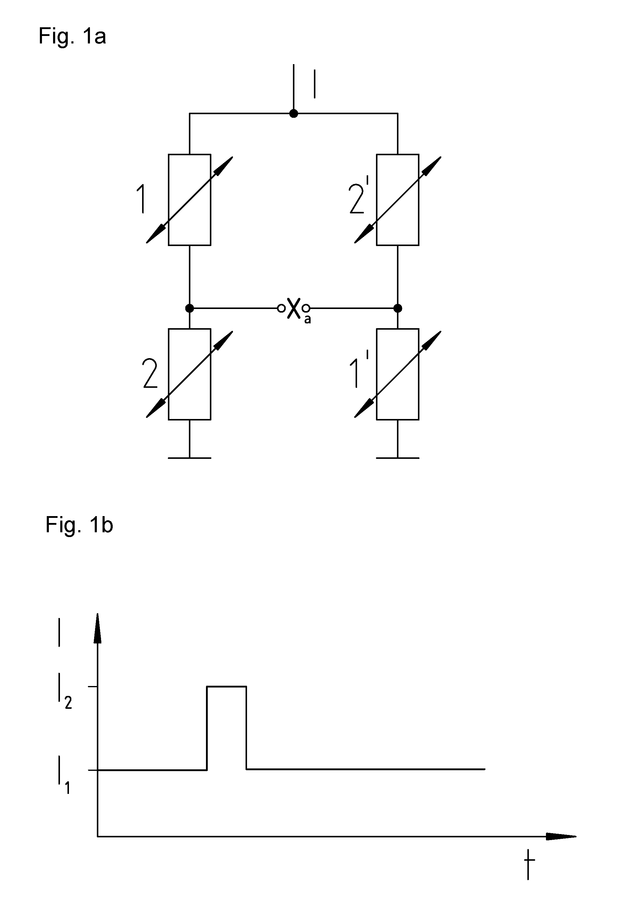
[0033]FIG. 1a shows a circuit diagram for operating a thermal conductivity detector with a Wheatstone bridge. A total of four chambers with gas are shown, chambers 1 and 1′ designating chambers with measuring gas and chambers 2 and 2′ designating chambers with the known reference or carrier gas. There is thus one cell with measuring gas and one cell with the known reference or carrier gas in each branch of the bridge (to the left and right in FIG. 1a). The bridge voltage Xa is tapped between the two branches of the bridge. It is possible to infer the thermal conductivity of the measuring gas in the measuring chambers 1 and 1′ from the measured bridge voltage Xa. In turn, the thermal conductivity depends on the material composition of the gas mixture in the measuring chambers and thus also on the concentrations of the individual gases and the temperature. The temperature can be set by way of the intensity of the current flowing through the heating wires in the gas chambers. The four ...


PUM

PropertyMeasurementUnit
concentrationsaaaaaaaaaa
thermal conductivity detectoraaaaaaaaaa
bridge voltage xaaaaaaaaaaa

Abstract

A method for the determination of gas concentrations xi in a gas mixture using a thermal conductivity detector with a Wheatstone bridge. It comprises the following method steps: measuring the bridge voltage Xa; correcting the measured values for the bridge voltage Xa, in particular with respect to drift; determination of the thermal conductivity of the gas mixture; and determination of at least one gas concentration xi. Preferably, an automatic zero-point correction and an automatic measuring range end value correction occur within the framework of the correction.

Description

CROSS-REFERENCE TO RELATED APPLICATIONS[0001]The present application claims priority under 35 U.S.C. §119 of German Patent Application No. 10 2010 046 829.0, filed on Sep. 29, 2010, the disclosure of which is hereby incorporated herein by reference in its entirety.FIELD OF THE INVENTION[0002]The present invention relates to a method for determining gas concentrations in a gas mixture using a thermal conductivity detector with a Wheatstone bridge. The method is especially suitable for use in laboratory environments. It can especially be used in an incubator for the precise determination of gas concentrations in a gas mixture. The present invention further relates to a computer program product with a program code for performing the method for determining gas concentrations in a gas mixture, the use of the method for determining gas concentrations in a gas mixture for characterizing the atmosphere in an incubator and an incubator with a correspondingly adapted gas concentration determi...

Claims


Application Information

Patent Timeline
Patent Type & Authority Applications(United States)
IPC IPC(8): G01N25/18
CPCG01N27/18
Inventor GATZMANGA, HEINZWOLFF, ROBERTOSTAHL, HERMANN
Owner THERMO ELECTRONICS LED GMBH
Why Eureka
Try Eureka