Variable Displacement Compressor

a compressor and variable displacement technology, applied in the direction of positive displacement engines, reciprocating piston engines, liquid positive displacement engines, etc., can solve the disadvantages of sealing parts and the durability of rotational and drive parts

Inactive Publication Date: 2012-03-29
SANDEN CORP
View PDF2 Cites 29 Cited by
  • Summary
  • Abstract
  • Description
  • Claims
  • Application Information

AI Technical Summary

Benefits of technology

[0014]Accordingly, an object of the present invention is to provide a variable displacement compressor excellent in performance and property which can achieve to improve the performance of the compressor such as reduction of pulsation and improvement of durability and resistance to pressure and which can control the tilt angle of a swash plate at a target tilt angle more smoothly and precisely via an axial movement member.Means for Solving the Problems
[0026]Further, in the variable displacement compressor according to the present invention, it is preferred that respective parts are set so that a total balance of a couple moment generated in a tilt angle changing plane of the swash plate by at least rotational and reciprocal movement of the respective parts becomes one in a direction for decreasing tilt angle in every tilt angle of the swash plate. In such a structure, since the total balance of the couple moment of the swash plate due to the rotational and reciprocal movements of respective parts always acts in a direction for decreasing the tilt angle of the swash plate, namely, since it always acts in desired one direction, as long as the aforementioned intermediate pressure applied to the other end of the axial movement member is controlled, it becomes possible to control the tilt angle of the swash plate at a target tilt angle easily and precisely. In other words, as aforementioned, because the intermediate pressure applied to the other end side of the axial movement member cannot be made lower than the suction pressure applied to the opposite side, only by the gas pressures applied to both end sides of the axial movement member, the axial movement member can be operated only in a direction for increasing the cam angle (the tilt angle of the swash plate). However, if it is set so that the total balance of the couple moment of the swash plate due to the rotational and reciprocal movements of the respective parts always acts in a direction for decreasing the tilt angle of the swash plate, by the control of the intermediate pressure, the cam angle (the tilt angle of the swash plate) can be easily controlled at an arbitrary desired angle. Further, because a couple moment for decreasing the tilt angle always acts to the swash plate, for example, in case where the compressor operation off mode is required to be kept, etc., only by driving and rotating the compressor the swash plate is naturally changed in angle in a direction of a minimum tilt angle, and after changed to the minimum tilt angle, the swash plate is maintained at the minimum tilt angle.
[0028]Thus, in the variable displacement compressor according to the present invention, by the structure where the suction gas is taken into the crank chamber through the suction path opening into the crank chamber, noise originating from pulsation of suction can be prevented or reduced by functioning the crank chamber with a great capacity as a suction chamber. Further, because a suction throttle valve is omitted, the design freedom on layout of cylinder head can be increased. Further, by the structure where the suction gas is introduced into the suction chamber formed in the cylinder head from the crank chamber through the communication path, because it becomes possible to reduce the capacity of the suction chamber, and by the amount of the reduction, the capacity of the discharge chamber can be increased, noise originating from pulsation of discharge can also be prevented or reduced. Further, because the temperature and pressure in the crank chamber can be reduced, the durability of the respective drive parts and the pressure resistance of a housing part can be improved, and it becomes possible to thin the housing part and make the whole of the compressor small and light in weight. Further, by the structure where the pressure in the crank chamber and the intermediate pressure controlled by the intermediate pressure control mechanism are applied to the respective ends of the axial movement member and the axial position of the axial movement member is controlled precisely, through the position control, it becomes possible to control the tilt angle of the swash plate and the displacement of the compressor stably and precisely. In particular, if it is set so that the total balance of the couple moment generated by the rotational and reciprocal movements of the respective parts in the compressor is always directed in a direction for decreasing the cam angle (a direction for decreasing the tilt angle of the swash plate, namely, a direction for decreasing the displacement), through the axial position control of the axial movement member controlled only by the control of the intermediate pressure, it becomes possible to perform the displacement control easily and more smoothly, and in particular, a starting shock at a high-speed driving time and the like can be relieved, and a smooth starting property can be obtained. Furthermore, by setting such a total balance of couple moment, it becomes possible to reduce the consumption power in case of a clutchless type compressor.

Problems solved by technology

In the variable displacement compressor having such a conventional structure, because a control gas with relatively high temperature and high pressure, which is reduced in pressure from the discharge pressure, is introduced into the crank chamber, the durability for rotational and drive parts and for a seal portion is disadvantageous.

Method used


Image

  • Variable Displacement Compressor
  • Variable Displacement Compressor
  • Variable Displacement Compressor

Examples


Embodiment Construction

[0043]Hereinafter, concrete embodiments of the present invention will be explained referring to figures.

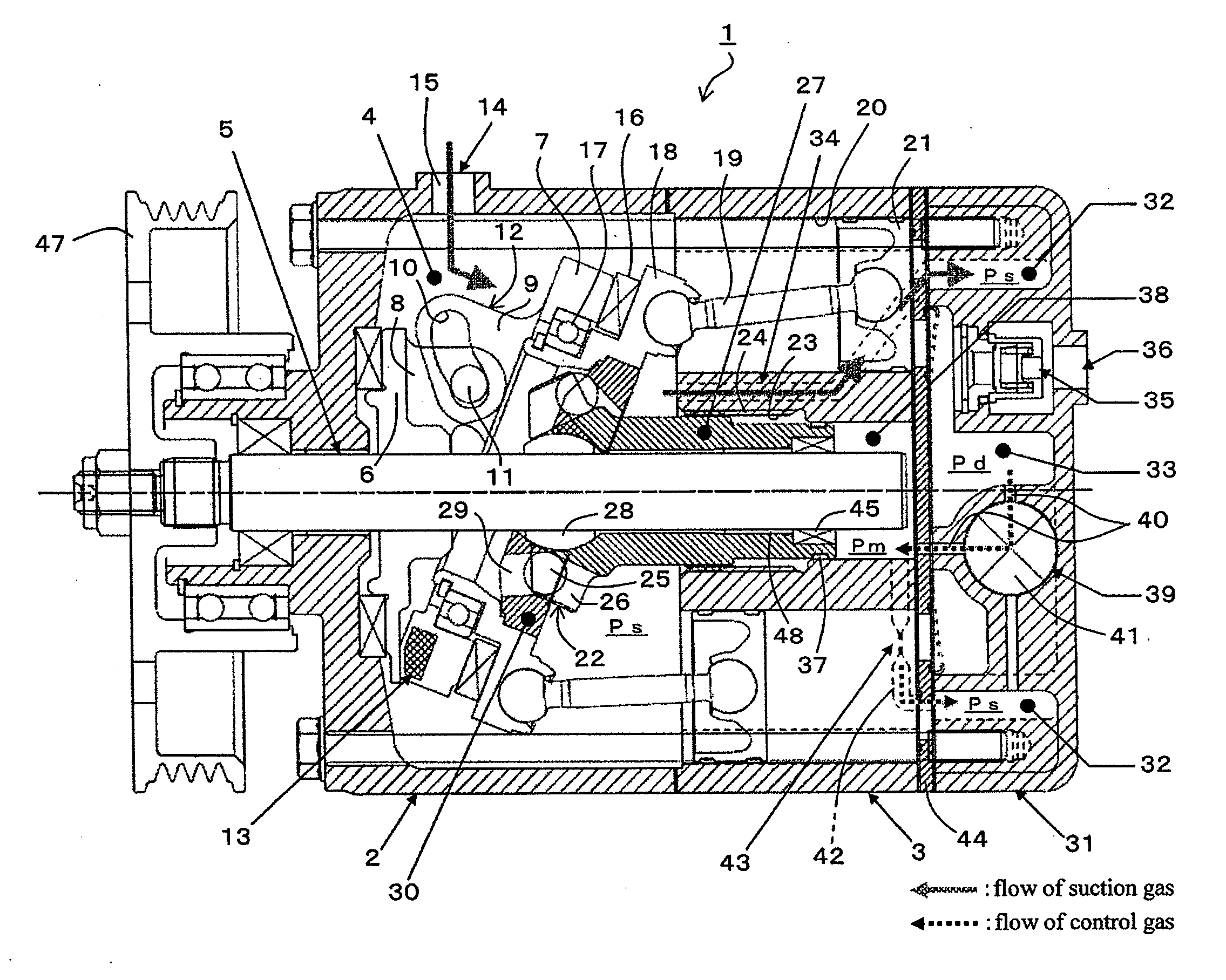
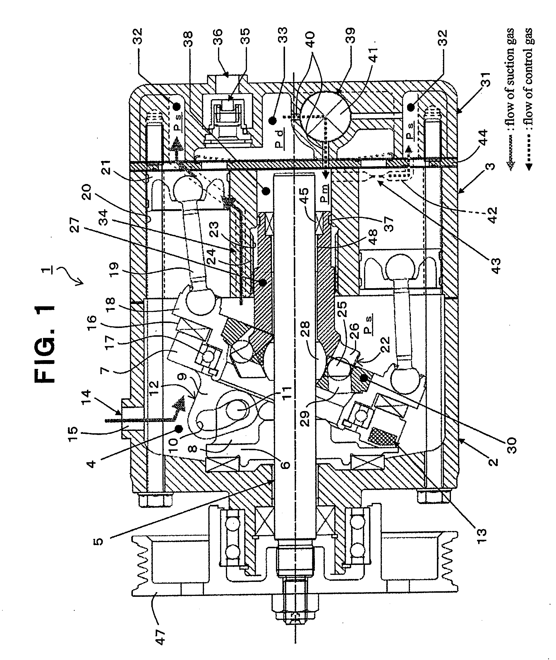
[0044]FIGS. 1 to 6 show a variable displacement compressor according to a first embodiment of the present invention. FIG. 1 shows a state at the time of a maximum displacement (a maximum cam angle [a maximum swash plate angle]) of a variable displacement compressor 1, and FIG. 3 shows a state at the time of a minimum displacement (a minimum cam angle [a minimum swash plate angle]). In FIG. 1, a main shaft 5 is inserted into a crank chamber 4 formed by a front housing 2 and a cylinder block 3, relatively to main shaft 5, provided is a rotor 6 which is fixed to main shaft 5 and rotated integrally with main shaft 5, and disposed is a swash plate 7 which can be changed in its tilt angle relative to main shaft 5 and which can be rotated integrally with main shaft 5. Between rotor 6 and swash plate 7, provided is a hinge mechanism 12 forming a sliding mechanism wherein an arm 8 extendin...


PUM


Abstract

Disclosed is a variable displacement compressor having improved compressor performance such as reduced pulsation and improved durability and resistance to pressure and allowing smooth and high-precision control of a swash plate tilt angle at a target tilt angle by using an axial movement member. The variable displacement compressor is provided with a cylinder head in which a suction chamber and a discharge chamber are formed, a cylinder block having a cylinder bore into which a piston is inserted at a condition capable of being reciprocated, a crank chamber formed by the cylinder block and a front housing, a swash plate which is disposed in the crank chamber and which is rotated with a main shaft and is supported so that the tilt angle thereof can be changed relative to the main shaft, and a movement conversion mechanism for converting the rotational movement of the swash plate to the reciprocating movement of the piston, wherein: a suction path for intake of a suction gas into the compressor is formed so as to open into the crank chamber; a communication path for communicating the crank chamber and the suction chamber is provided in the cylinder block; around the main shaft, an axial movement member is provided that can move in a direction along the axis of the main shaft in an essentially one to one correspondence with the tilt angle of the swash plate; the axial movement member is disposed such that one end is applied with the pressure in the crank chamber, and the other end is applied with an intermediate pressure between the pressure in the discharge chamber and the pressure in the suction chamber; and an intermediate pressure control mechanism which can control the intermediate pressure is also provided.

Description

TECHNICAL FIELD OF THE INVENTION[0001]The present invention relates to a variable displacement compressor, and specifically, to a variable displacement compressor in which reduction of pulsation and improvement of durability and resistance to pressure can be performed and a tilt angle of a swash plate can be controlled more smoothly and precisely via an axial movement member.BACKGROUND ART OF THE INVENTION[0002]A variable displacement compressor is well known which is provided with a cylinder head in which a suction chamber and a discharge chamber are formed, a cylinder block having a cylinder bore into which a piston is inserted at a condition capable of being reciprocated, a crank chamber formed by the cylinder block and a front housing, a swash plate which is disposed in the crank chamber and which is rotated with a main shaft and is supported so that a tilt angle thereof can be changed relative to the main shaft, and a movement conversion mechanism for converting rotational move...

Claims


Application Information

Patent Timeline
Patent Type & Authority Applications(United States)
IPC IPC(8): F01B3/02
CPCF04B27/1054F04B27/1804F04B2027/1859F04B2027/1831F04B2027/185F04B2027/1813F04B27/08F04B27/14
Inventor UCHIKADO, IWAO
Owner SANDEN CORP
Why Eureka
Try Eureka