Adjustable Racking System for Solar Array and Method of Construction of a Solar Array

a solar array and adjustable technology, applied in the direction of heat collector mounting/support, solar thermal energy generation, etc., can solve the problems of difficult and expensive structure installation, and limited solar energy absorption potential, so as to control the amount of sunlight reaching, the effect of minimising the negative environmental impa

Active Publication Date: 2012-03-29
HYPERION SYST
View PDF22 Cites 10 Cited by
  • Summary
  • Abstract
  • Description
  • Claims
  • Application Information

AI Technical Summary

Benefits of technology

[0012]In another embodiment, there is provided a mounting structure for supporting one or more solar panels above the ground with minimal negative environmental impact. The structure includes at least one pole having a bottom end penetrating the ground, and a top end extending above the ground, the at least one pole secured in the ground without a concrete footing. Such a structure also includes a spline mounted to the at least one pole, a yoke releasably secured to the spline such that the yoke may be released, moved to a different location along the spline, and re-secured to the spline, without being removed from the spline, and at least one solar panel mounted to the yoke, such that the yoke is movable along the spline so as to be relocateable, and so as to controllably moderate the amount of sunlight reaching the ground adjacent to the structure.

Problems solved by technology

Such fixed mounting limits the utility of the panel.
For example, such fixed mounting may limit the potential for maximum absorption of sunlight.
However, the space constraints of building-mounted make such structures difficult and expensive to install, in part because of their location.
Delivering the components of a solar panel and its support structure to a mounting location atop a building can be both expensive and dangerous.
The cost of delivering the materials may include heavy lifting equipment, for example, and require specialized construction skills.
In addition, structures located on roofs eventually will need to be disassembled and reinstalled when the life of the roof is exhausted and a new roof installed, which becomes time consuming and costly.
Traditional construction equipment and methods, however, typically involve heavy machinery, methods and materials that scar and disrupt the native environment—for example via disruption or extinction of flora and fauna.
Both the footings, and the equipment and processes used to make such support structures, disrupt and often ruin the native environment.
Moreover, panels and panel arrays may limit the use of the ground or structure beneath.
In some cases, for example, arable land has been decommissioned from productive use due to the excessive shade created by solar panels and their mounting structures being positioned in contact with the ground.

Method used


Image

  • Adjustable Racking System for Solar Array and Method of Construction of a Solar Array
  • Adjustable Racking System for Solar Array and Method of Construction of a Solar Array
  • Adjustable Racking System for Solar Array and Method of Construction of a Solar Array

Examples


Embodiment Construction

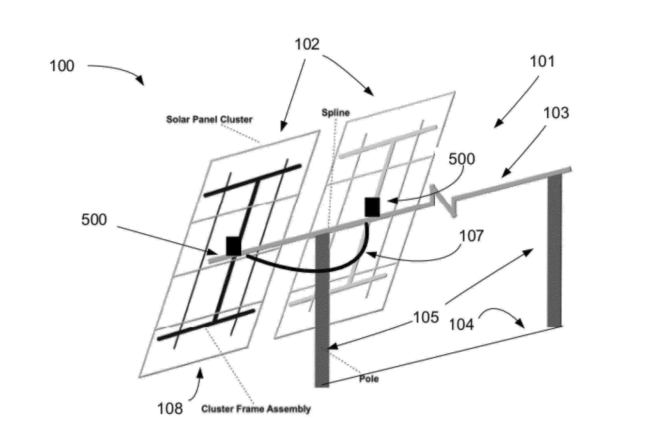
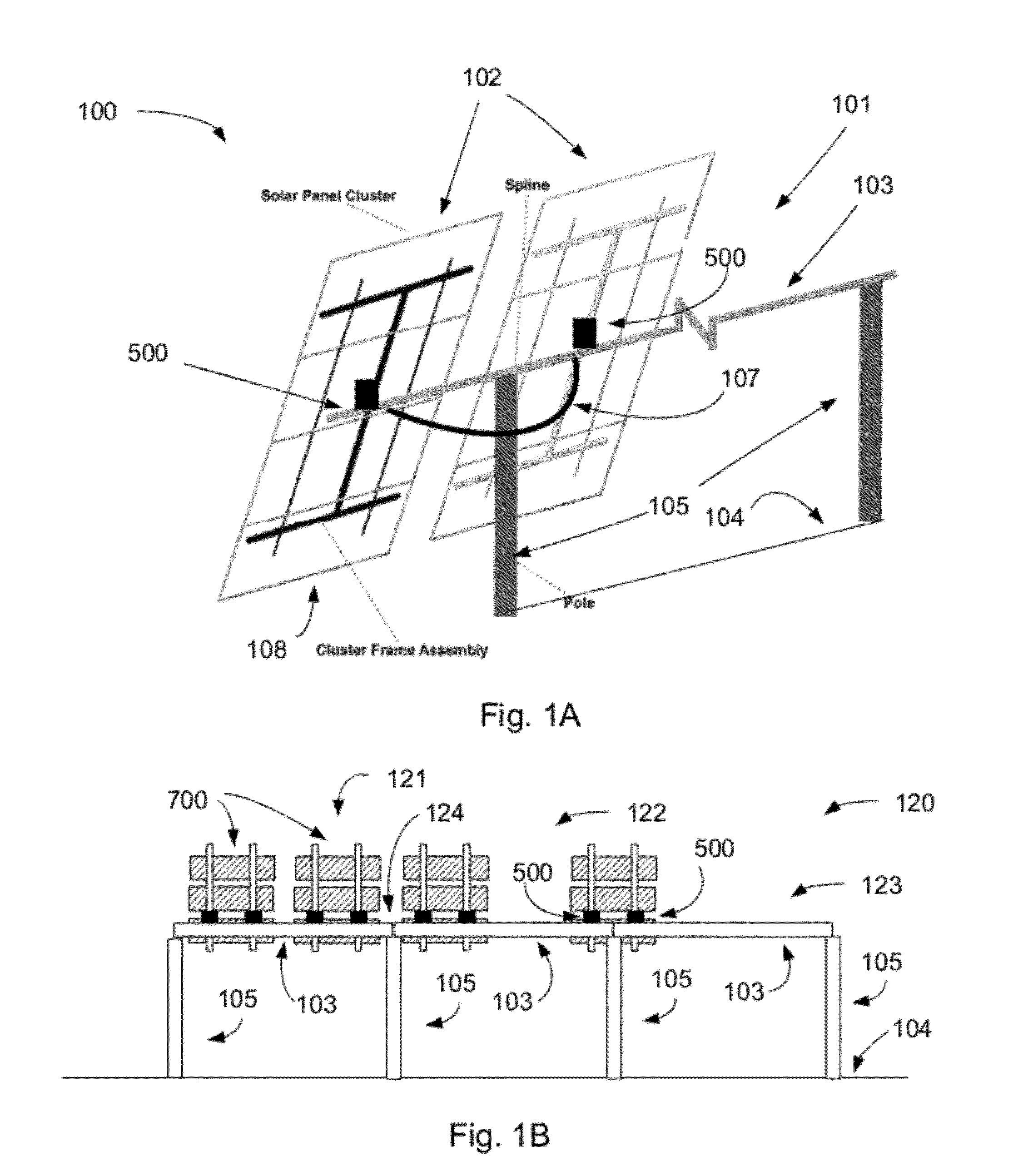
[0008]In a first embodiment, there is provided a yoke for mounting a solar panel or solar panel cluster to a spline on a solar panel mounting structure. The yoke includes at least a base portion, with a panel mounting frame coupled to the base portion, and arm portions coupled to the base portion and arranged to movably engage the spline, along with at least one solar panel mounted to the panel mounting frame.

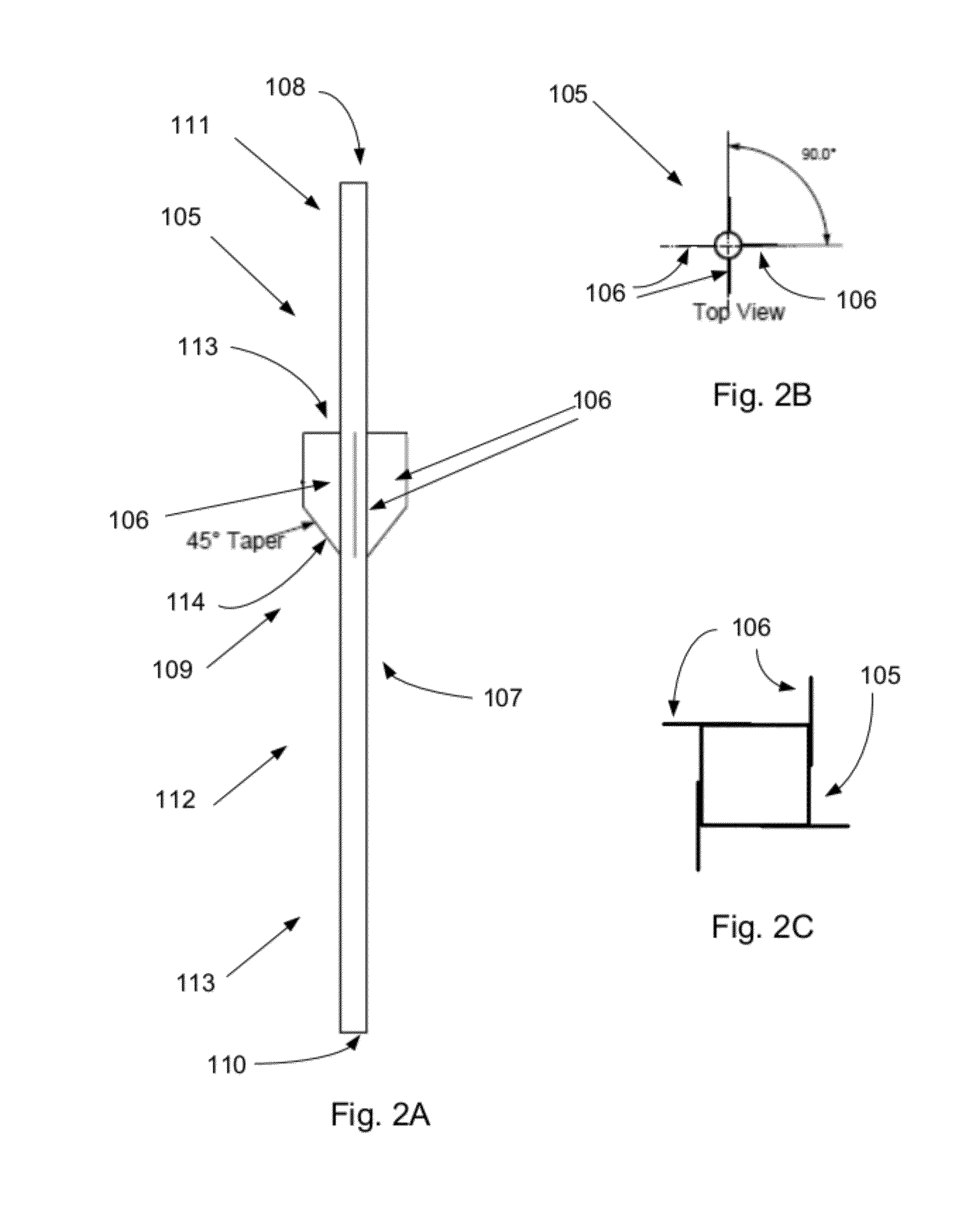
[0009]In some embodiments, the panel mounting frame includes a base bracket and a panel bracket. In various embodiments, the base bracket is fixedly attached to the base portion. In some embodiments the panel bracket is rotatably coupled to the base bracket. In some embodiments, the panel bracket includes notches to engage a solar panel.

[0010]In various embodiments, the base portion has at least one securing arm extending around the circumference of the spline, while in some embodiments the at least one securing arm is a U-shaped member secured to the base portion, such that an...


PUM

PropertyMeasurementUnit
diameteraaaaaaaaaa
diameteraaaaaaaaaa
sizeaaaaaaaaaa

Abstract

A structure for supporting an array of solar panels above a surface comprises finned poles, a horizontal spline, and a number of movable yokes coupling each of the solar panels to the spline, such that the solar panels may be secured to the spline, and later repositioned along the spline and re-secured to the spline. A pole includes one or more fins in a central portion, to stabilize the pole when set into the ground. The cross-section of the spline may take a variety of shapes, including quadrilateral shapes and conic sections. Constructing a solar array involves using commonplace, readily accessible materials, and construction equipment and methods with low-environmental-impact, all to produce an attractive, easy to construct environmentally friendly installation.

Description

PRIORITY[0001]This patent application claims priority from provisional U.S. patent application No. 61 / 385,686, filed Sep. 23, 2010, entitled, “Adjustable Racking System for Solar Array,” and naming James David Marley as inventor [practitioner's file 3604 / 101], the disclosure of which is incorporated herein, in its entirety, by reference.TECHNICAL FIELD[0002]The present invention relates to photovoltaic panel arrays, and more particularly to structures and methods for mounting photovoltaic panels.BACKGROUND ART[0003]Photovoltaic panels (which may be known as “solar panels,” each of which may include one or more photovoltaic cells or “solar cells”) are typically mounted on structures and oriented to facilitate their maximum exposure to sunlight.[0004]Such panels are typically arranged to efficiently absorb available sunlight. To that end, some panel mounting systems may allow the panel to pivot up or down, or left to right, to track the sunlight. Aside from an ability to pivot in plac...

Claims


Application Information

Patent Timeline
Patent Type & Authority Applications(United States)
IPC IPC(8): F24J2/52B23P17/00
CPCY02B10/20F24J2/5232F24J2/5252F24J2/526Y10T403/7188Y02E10/47Y02E10/50H02S20/00Y10T29/49826F24J2/5264F24S25/12F24S25/63F24S25/65F24S25/70H02S20/10
Inventor MARLEY, JAMES DAVID
Owner HYPERION SYST
Why Eureka
Try Eureka