Hybrid battery module and battery management method

a battery module and hybrid technology, applied in the field of hybrid battery modules, can solve the problems of not providing two sets of batteries may not charge to each other, and the load cannot provide power to the load at the same time, so as to prevent the damage of the battery and increase the service life of the battery module

Inactive Publication Date: 2012-03-29
LITE ON CLEAN ENERGY TECH
View PDF2 Cites 45 Cited by
  • Summary
  • Abstract
  • Description
  • Claims
  • Application Information

AI Technical Summary

Benefits of technology

[0007]The present invention provides a hybrid battery module and a method of controlling the same. The hybrid battery module may have two different types of energy storage elements, such as two different types of secondary batteries, so as to choose the most suitable power source to provide power in accordance with characteristics of the energy storage elements while the load is under different power requirements. For example, while an electric vehicle is climbing a slope or is accelerating, a power type battery module is used to provide output power; while the electric vehicle

Problems solved by technology

Since under operating process the internal resistances and power of the power type secondary batteries and the energy type secondary batteries are different, loads may not recharge these two types of batteries simultaneously.
When the power of the power type secondary battery is insufficient, it may not provide large output power instantaneously; while th

Method used


Image

  • Hybrid battery module and battery management method
  • Hybrid battery module and battery management method
  • Hybrid battery module and battery management method

Examples


first embodiment

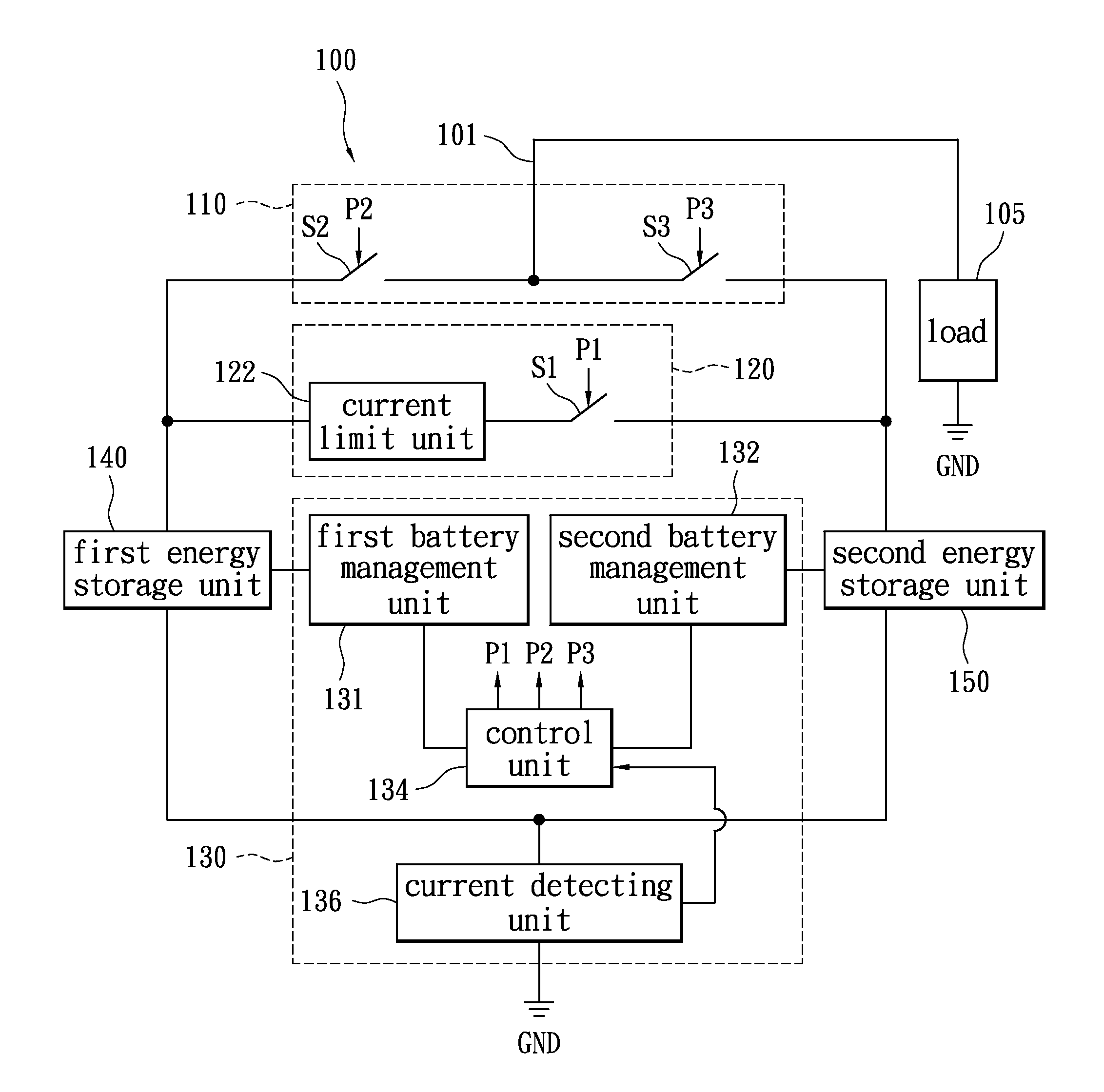
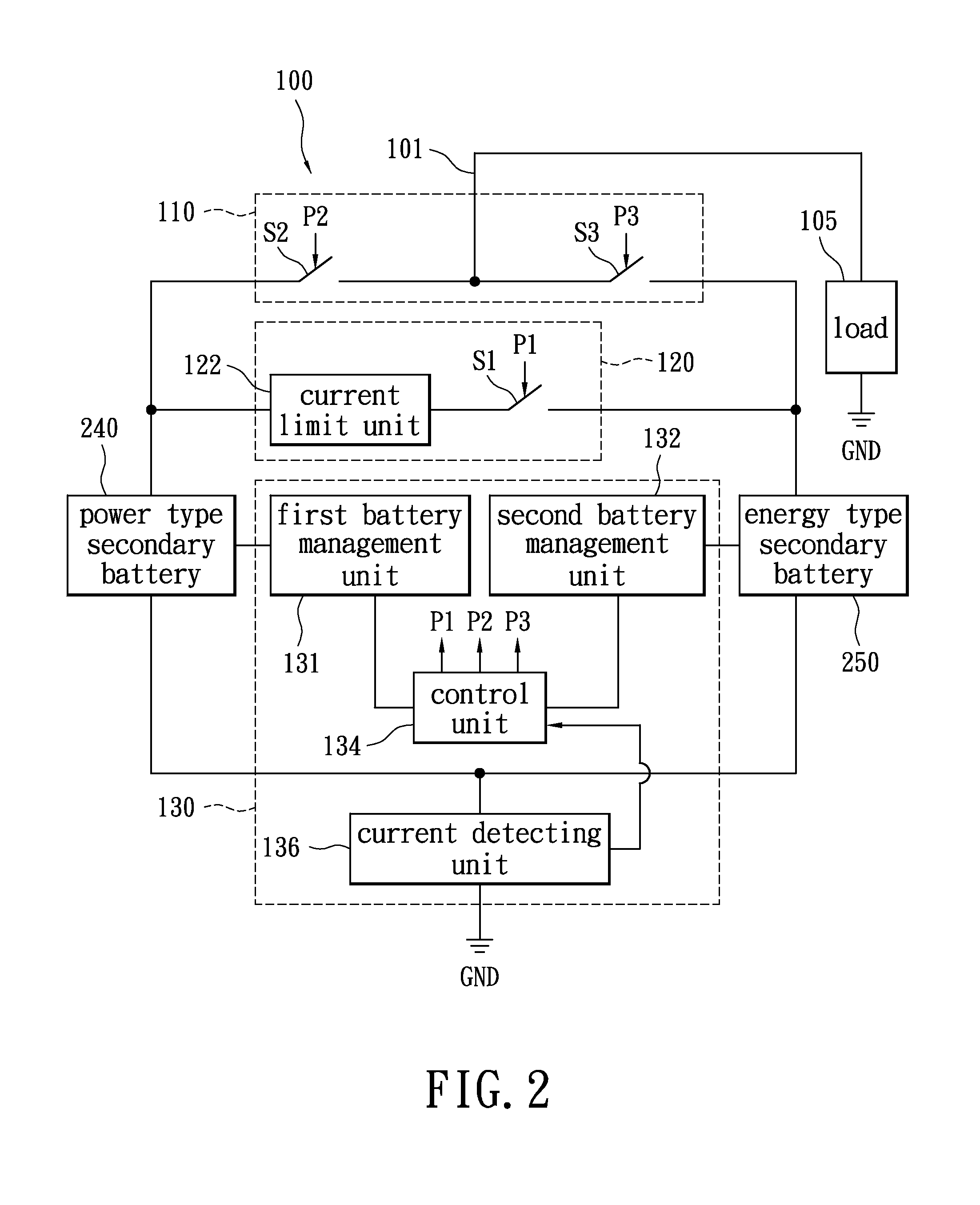
[0020]Please refer to FIG. 1, in which a schematic diagram of a hybrid battery module in accordance with certain aspects of the present invention is illustrated. A hybrid battery module 100 has a load terminal 101 which may connect to the load 105 for supplying power. The hybrid battery module 100 comprises a power supply switching unit 110, a charging unit 120, a battery management circuit 130, a first energy storage unit 140, and a second energy storage unit 150. The power supply switching unit 110 includes a switch S2 and a switch S3, wherein the switch S2 is coupled between the first energy storage unit 140 and the load terminal 101. The switch S3 is coupled between the load terminal101 and the second energy storage unit 150. The charging unit 120 includes a current limit unit 122 and a switch S1, wherein the current limit unit 122 and the switch S1 are coupled in series between the first energy storage unit 140 and the second energy storage unit 150. The battery management circ...

second embodiment

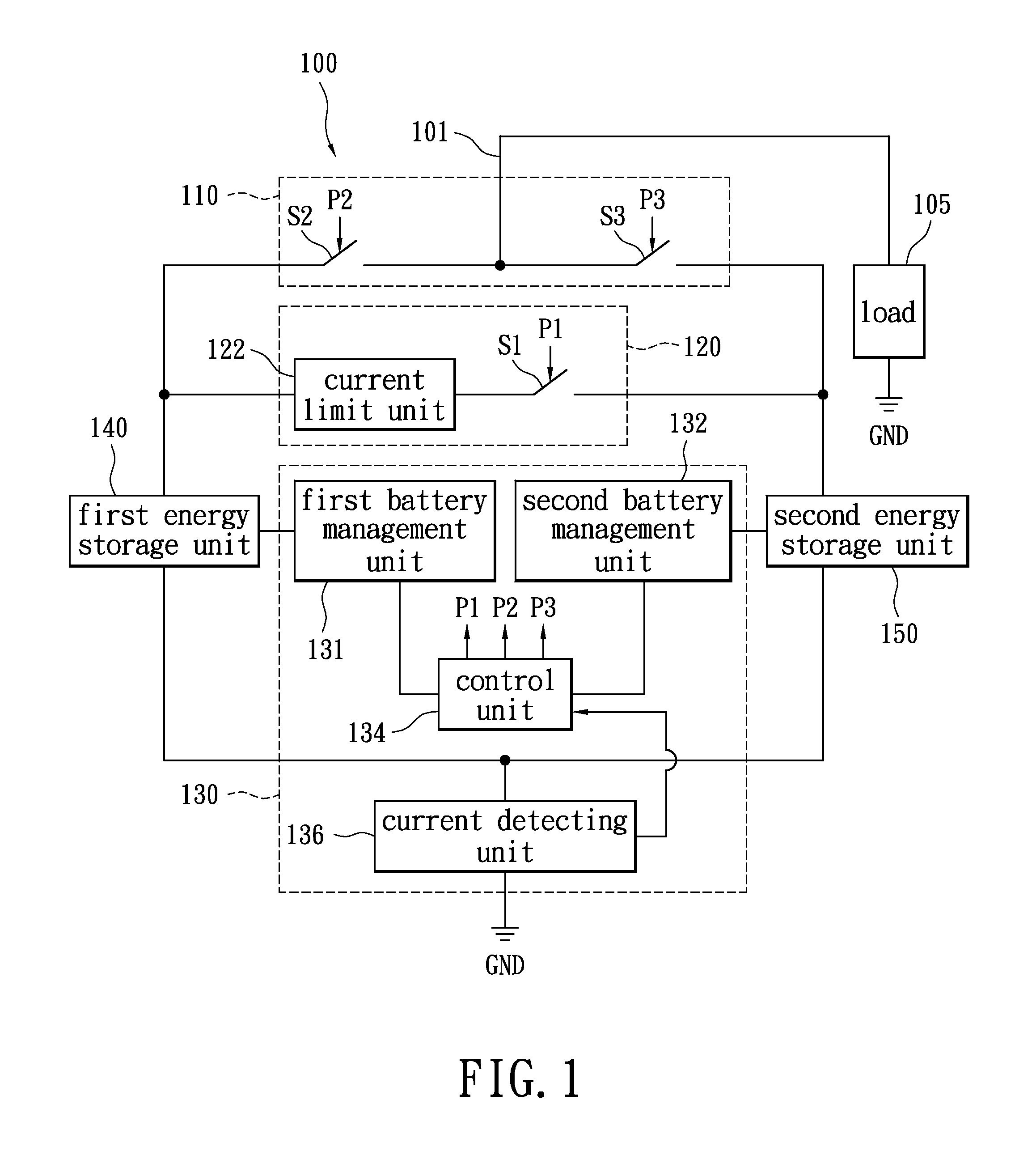
[0032]Please refer to FIG. 3, in which a schematic diagram of another embodiment of the hybrid battery module of the present invention is illustrated. The major difference between FIG. 1 and FIG. 3 is a supercapacitor 340 and a secondary battery 350. The first energy storage unit 140 and the second energy storage unit 150 as shown in FIG. 1 may be implemented by the supercapacitor or other energy storage component as shown in FIG. 3. The supercapacitor 340 and the secondary battery 350 are used to implement the first energy storage unit 140 and the second energy storage unit 150 as shown in FIG. 1, respectively. The supercapacitor 340 has the effect for storing energy and discharging energy rapidly. Therefore, as long as the capacitance value of the supercapacitor 240 is large enough, a large power output is generated to drive the load 105. The supercapacitor 240 is also known as an extra large capacitance capacitor, e.g., an electric double-layer capacitor, but is not limited there...

third embodiment

[0033]The current limit unit 122 shown in FIG. 1 may be replaced by a bidirectional DC-DC power converter as shown in FIG. 4. FIG. 4 illustrates a schematic diagram of the embodiment in accordance with the hybrid battery module which applies a bidirectional DC-DC power converter 422 to replace the current limit unit 122 according to the present invention. The major difference between FIG. 1 and FIG. 4 is the bidirectional DC-DC power converter 422 which is coupled between the first energy storage unit 140 and the switch S1, for performing power conversion. The bidirectional DC-DC power converter 422 may achieve the effect of power transmission by adjusting the output power according to the states of charge of the first energy storage unit 140 and the second energy storage unit 150, the battery types, and the internal resistances. For example, as the power type secondary battery charges the energy type secondary battery, the bidirectional DC-DC power converter utilizes pulse width mo...


PUM


Abstract

A hybrid battery module and a battery management method are provided. The hybrid battery module comprises a first energy storage unit, a second energy storage unit, and a charging unit. The charging unit is coupled between the first energy storage unit and the second energy storage unit for selectively providing a charging path between the first energy storage unit and the second storage unit. The first energy storage unit and the second energy storage unit transmit the energy stored therein to each other through the charging unit to maintain optimum power statuses thereof.

Description

BACKGROUND OF THE INVENTION[0001]1. Field of the Invention[0002]The present invention relates to a battery module; in particular, to a hybrid battery module and a battery management method which are suitable for electric vehicles.[0003]2. Description of Related Art[0004]As human awareness of environmental protection and increasing energy conservation, electric vehicles have obvious advantages of reducing urban air pollution and have benefits such as quiet, zero pollution emission and without the use of gasoline. Electric vehicles require a combination of electrical, mechanical, and battery technologies, wherein battery technology is the most important one. Even though the battery modules of the electric vehicles may provide the necessary electric power to accelerate the electric vehicles, the battery modules are restricted by the energy density, the power density, also called specific power, and the battery charge and discharge mechanism, etc. Therefore, how to increase the service ...

Claims


Application Information

Patent Timeline
IPC IPC(8): H02J7/00
CPCB60L11/005B60L11/1864B60L11/1868H01M16/00H02J7/00Y02T10/7061H02J7/0068Y02T10/7005Y02T10/7022Y02T10/7066H02J7/0054B60L50/40B60L58/21B60L58/20H02J7/342H02J2310/48Y02T10/70
Inventor CHEN, JAN-GEECHENG, MING-WANG
Owner LITE ON CLEAN ENERGY TECH
Why Eureka
Try Eureka