Wireless charging coil structure in electronic devices

a charging coil and electronic device technology, applied in the direction of transformers, inductances, transportation and packaging, etc., can solve the problems of inconvenient wire placement, large space occupation, and significant increase in purchase costs, so as to improve overall power transmission stability, prevent electromagnetic emissions, and high permeability properties

Active Publication Date: 2012-03-29
FU TONG TECH
View PDF7 Cites 81 Cited by
  • Summary
  • Abstract
  • Description
  • Claims
  • Application Information

AI Technical Summary

Benefits of technology

[0015]A third object of the present invention is to ensure that the power energy transmitted by the induction coil of the PS and PR coil modules is transmitted only in the induction range between the first and second coils, thus making overall power transmission more stable. With high permeability properties of the magnetic conductor itself, this can effectively prevent electromagnetic emissions and avoid interference in normal operations of other electrical devices or equipments, and make it unnecessary to add shielding magnetic materials into non-induction range of the induction coil additionally for safety purpose.
[0016]Another object of the present invention is to wind in order of alternating winding directions the first and second coils which contains induction coils arranged in array, install the PS and PR coil modules at the inner bottom of side edges of the electronic device, and then utilize the induction range formed between the first coil and the second coil of the induction coil to induce electric currents. This allows the PS and PR coil modules to be used in planar electronic devices or other w...

Problems solved by technology

As handheld electronic devices are not manufactured according to the same specifications, however, different power supplies are needed to recharge these devices, and this may lead to significant increase in purchase costs.
If there are many power supplies at hand, it will not only cause inconvenience in putting wires in order, but also require considerable space, in addition to inconveniences in placing or carrying them.
When applied in circuits of induction type power supplies, such design will cause too much loss of magnetic field induction in the process of coupling and thus reduce conversion efficiency.
Though we may use larger E-shaped iron cores A to increase the effective sectional area, or increase the number of turns and enlarge air clearance to strengthen the ability of inducing electricity, it will result in overweight of E-shaped iron cores, making it inapplicable to handheld electronic devices that highlights portability.
Since wireless power energy is transmitted from both surfaces of the volute coil D at the PS end towards the volute coil D at the PR end, and cannot be fully received by the volute coil D at the PR end, the transmitted powe...

Method used


Image

  • Wireless charging coil structure in electronic devices
  • Wireless charging coil structure in electronic devices
  • Wireless charging coil structure in electronic devices

Examples


Embodiment Construction

[0026]To achieve the aforesaid objects and functions as well as the techniques adopted in the present invention and its fabrication, examples of the preferred embodiments of the present invention are given below to illustrate features and functions of the present invention in detail by referring to the accompanying drawings.

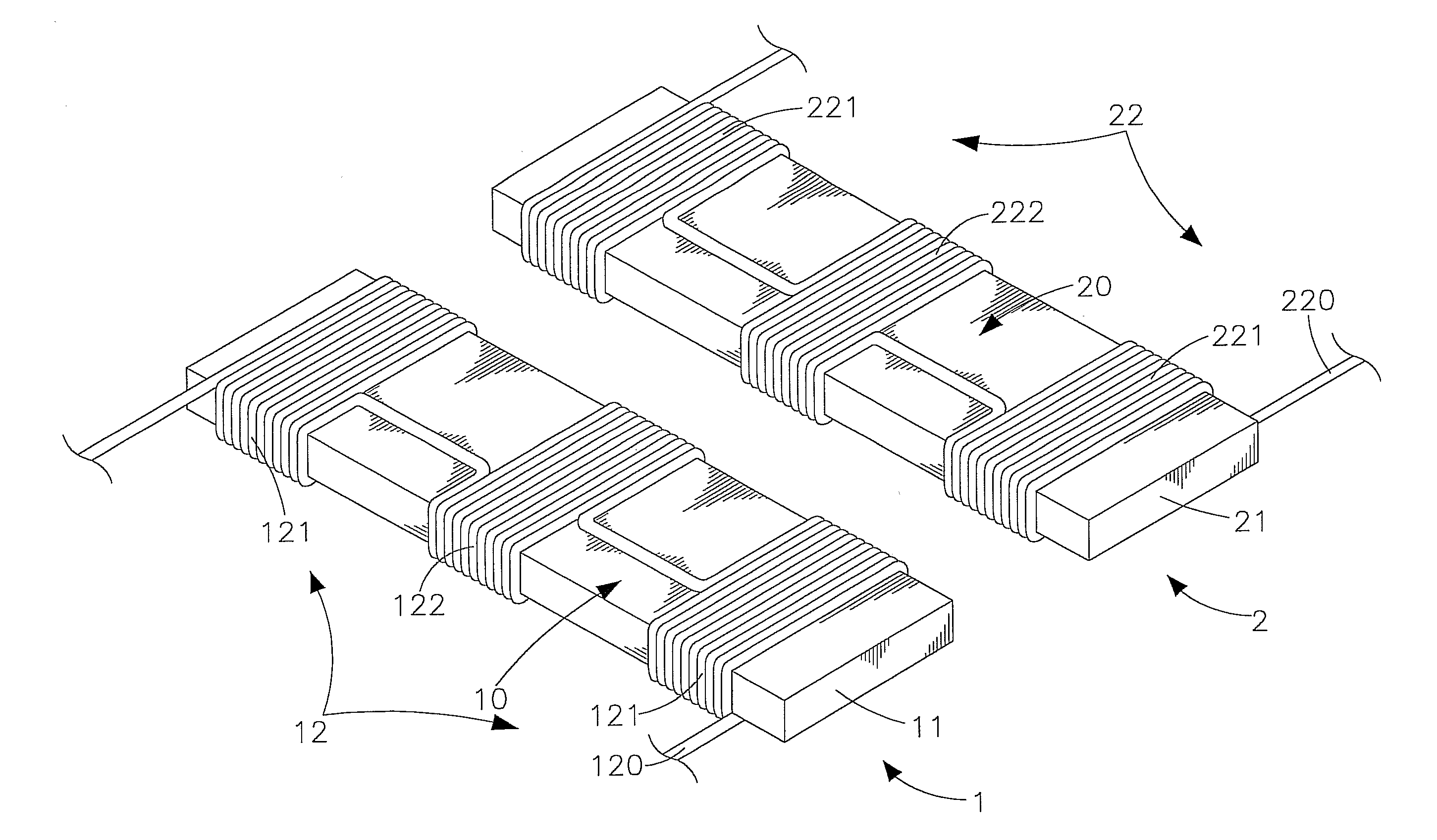
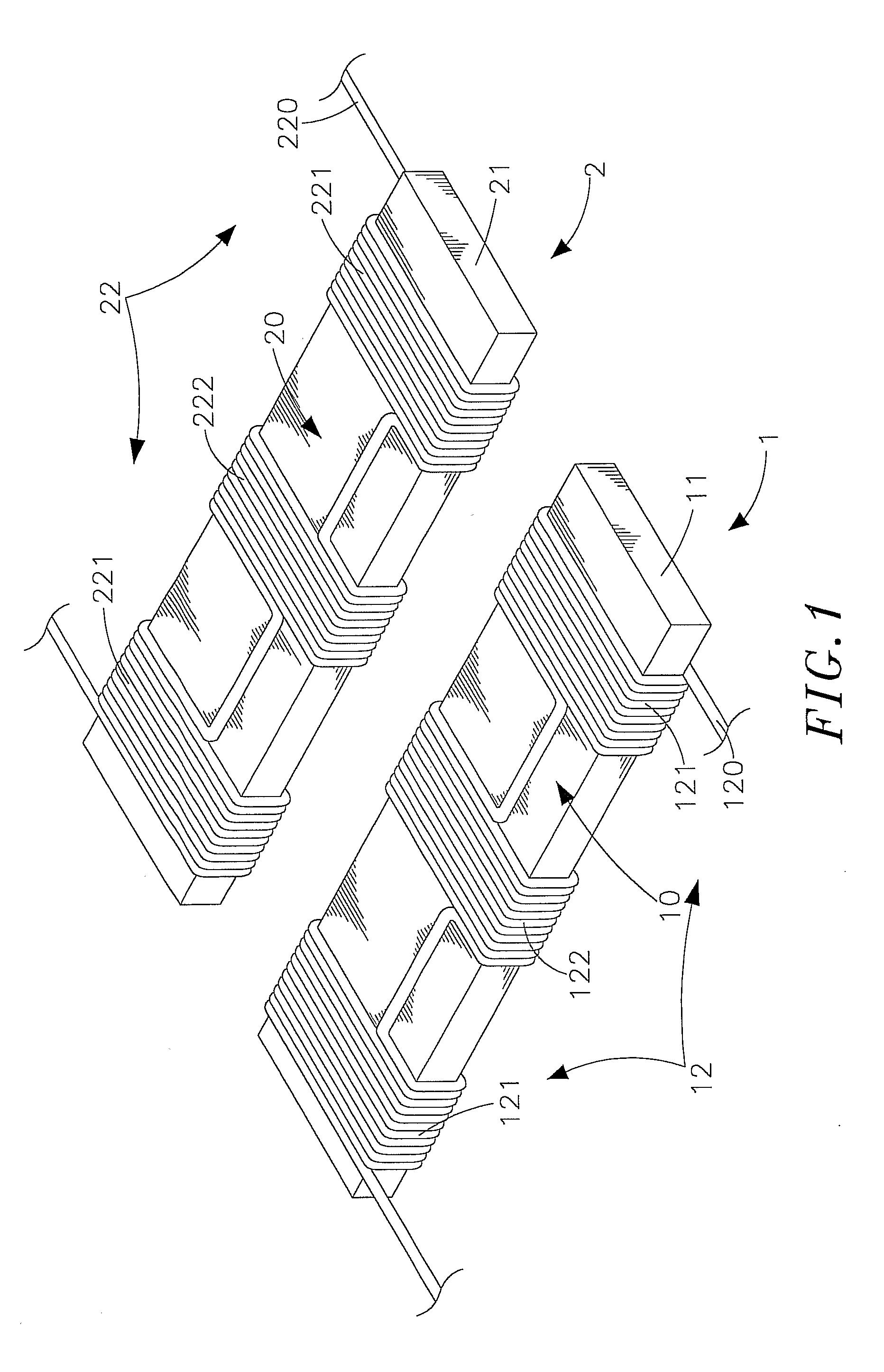
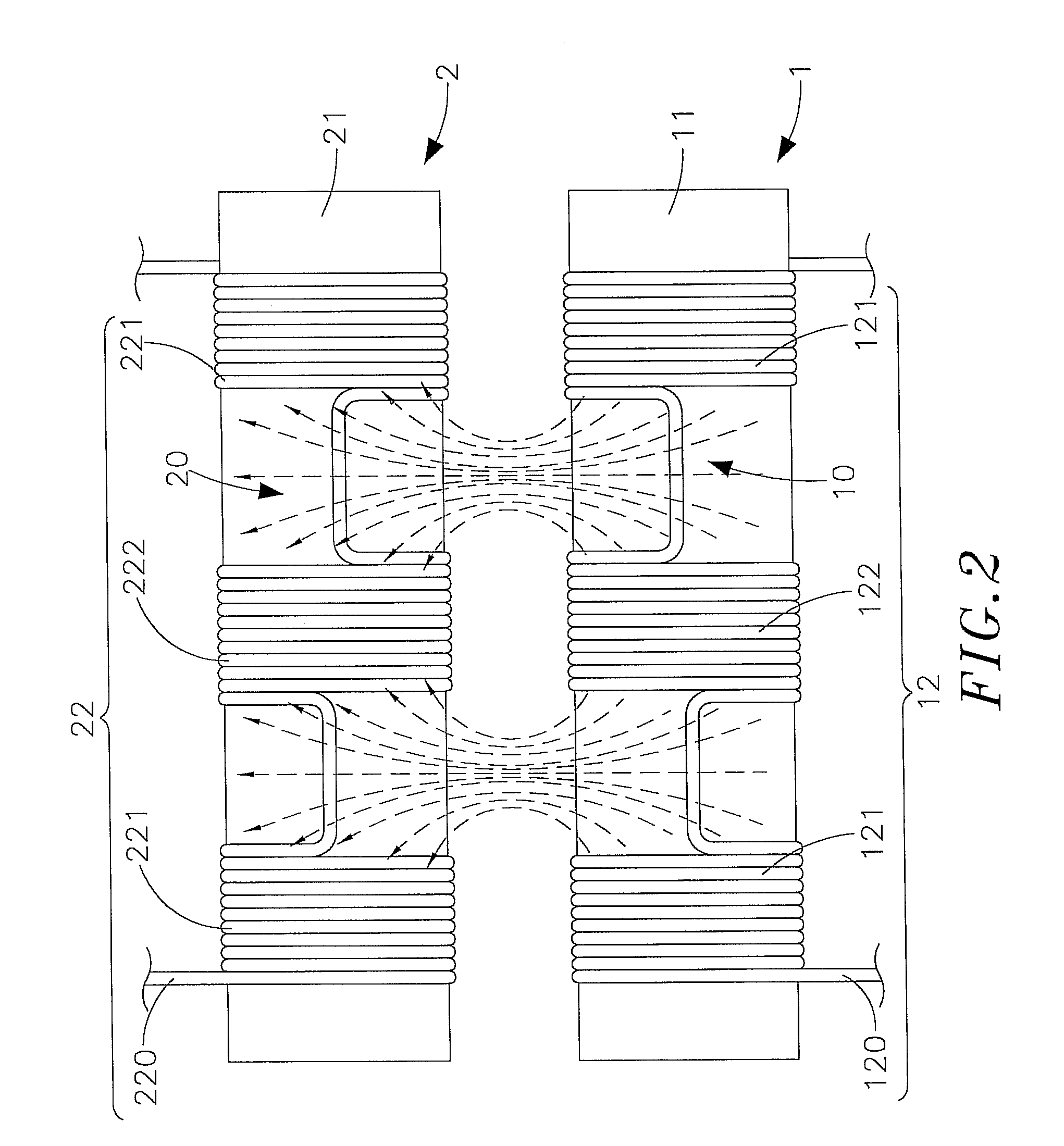
[0027]Refer to FIGS. 1, 2, 3 and 4, which are respectively a three-dimensional appearance drawing and a schematic drawing of electromagnetic induction according to the present invention, and three-dimensional appearance drawings according to one and another preferred embodiment of the present invention. As shown clearly in these figures, the present invention comprises a power sourcing (PS) coil module 1 and a power receiving (PR) coil module 2 (their major components and features will be illustrated in following paragraphs), wherein;

[0028]The PS coil module 1 contains a magnetic conductor 11 in the shape of a long bar and an induction coil 12, and an insulated w...


PUM


Abstract

The present inventions relates a wireless charging coil structure in electronic devices, comprising a PS coil module capable of emitting electromagnetic wave energy and a PR coil module capable of receiving power energy by electromagnetic induction. Each of the PS and PR coil modules includes a bar-shaped magnetic conductor, on which an insulated wire is wound into a first coil that is extended along the magnetic conductor to a given length and wound reversely into a second coil, thus producing an induction coil comprising at least the first and second coils. The induction range with given space formed between the first and second coils is used for electromagnetic induction to transmit signals and power energy. Such structure can be applied not only in planar handheld electronic devices, but also in other wireless power transmission systems that require narrow induction surface for power transmission.

Description

[0001]This application claims the priority benefit of Taiwan patent application number 100127754 filed on Aug. 4, 2011.BACKGROUND OF THE INVENTION[0002]1. Field of the Invention[0003]The present invention relates to a wireless charging coil structure in electronic products, particularly to a structure in which an insulated wire is wound on a magnetic conductor into a first coil, and the first coil is extended to a given length and then wound reversely into a second coil, so as to generate induced currents in the induction range between the first and second coils, making such structure applicable to transmission of power energy in devices with narrow inductive sections.[0004]2. Description of the Related Art[0005]Today, rapid developments in electronics and multimedia information result in the trend of lightness, thinness, shortness and miniaturization as well as multipurpose applications for handheld electronic devices, such as notebook and tablet computers, smart phones and persona...

Claims


Application Information

Patent Timeline
IPC IPC(8): H02J7/00H01F38/14
CPCH02J7/025H02J5/005H02J7/0042H02J50/402H02J7/0044H02J50/90H02J50/005H02J50/12
Inventor TSAI, MING-CHIUCHAN, CHI-CHE
Owner FU TONG TECH
Why Eureka
Try Eureka