
Data recovery device and method

Inactive Publication Date: 2012-03-29
SUNPLUS TECH CO LTD
View PDF0 Cites 0 Cited by
  • Summary
  • Abstract
  • Description
  • Claims
  • Application Information

AI Technical Summary

Benefits of technology

[0009]The invention is directed to a data recovery device, in which a data mapping unit is used to individually compensate an abnormal radio frequency (RF) signal, so as to improve a recognition degree of the RF signal.
[0015]According to the above descriptions, in the invention, the filtering-equalizing unit is first used to compensate the gain values of the sampling data points, and then the data mapping unit is used to individually compensate the signals still having excessively small gain values. In this way, not only the abnormal RF signal (for example, the RF signal with an excessively short period length) can be individually compensated, but also the normal RF signals are not influenced. Therefore, the recognition degree of the RF signal can be improved.

Problems solved by technology

When an optical storage system reads a radio frequency (RF) signal, it is liable to be influenced by factors such as inter-symbol interference (ISI), electrical delay, aging of dyes on a disc, or scratching surface of the disc to cause a poor recognition, so that a recognition degree of the RF signal is influenced.
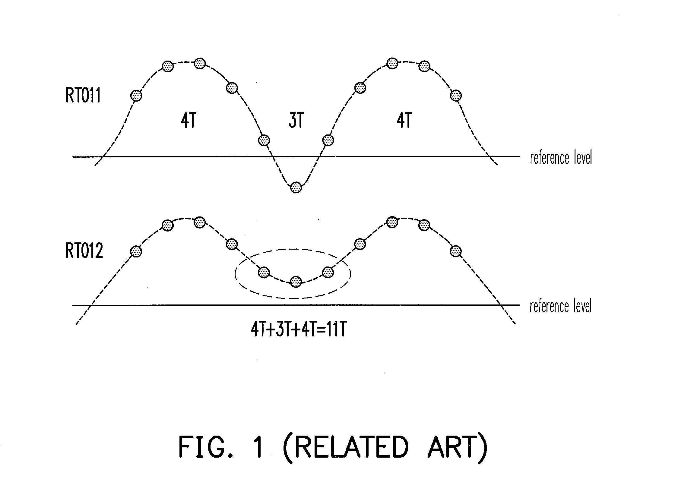
However, when the compensated 3 T signal is still excessively small, as that shown by a retiming data stream RTO2 at a lower portion of FIG. 1, a minimum point of the 3 T signal cannot be lower than a reference level.
In other words, regarding the abnormal RF signal (for example, the RF signal with an excessively short period length), the existing recovery device can only compensate the RF signal by increasing the gain value.
However, when the gain value is not great enough, the optical storage system still cannot obtain the original data.

Method used


Image

  • Data recovery device and method
  • Data recovery device and method
  • Data recovery device and method

Examples


Embodiment Construction

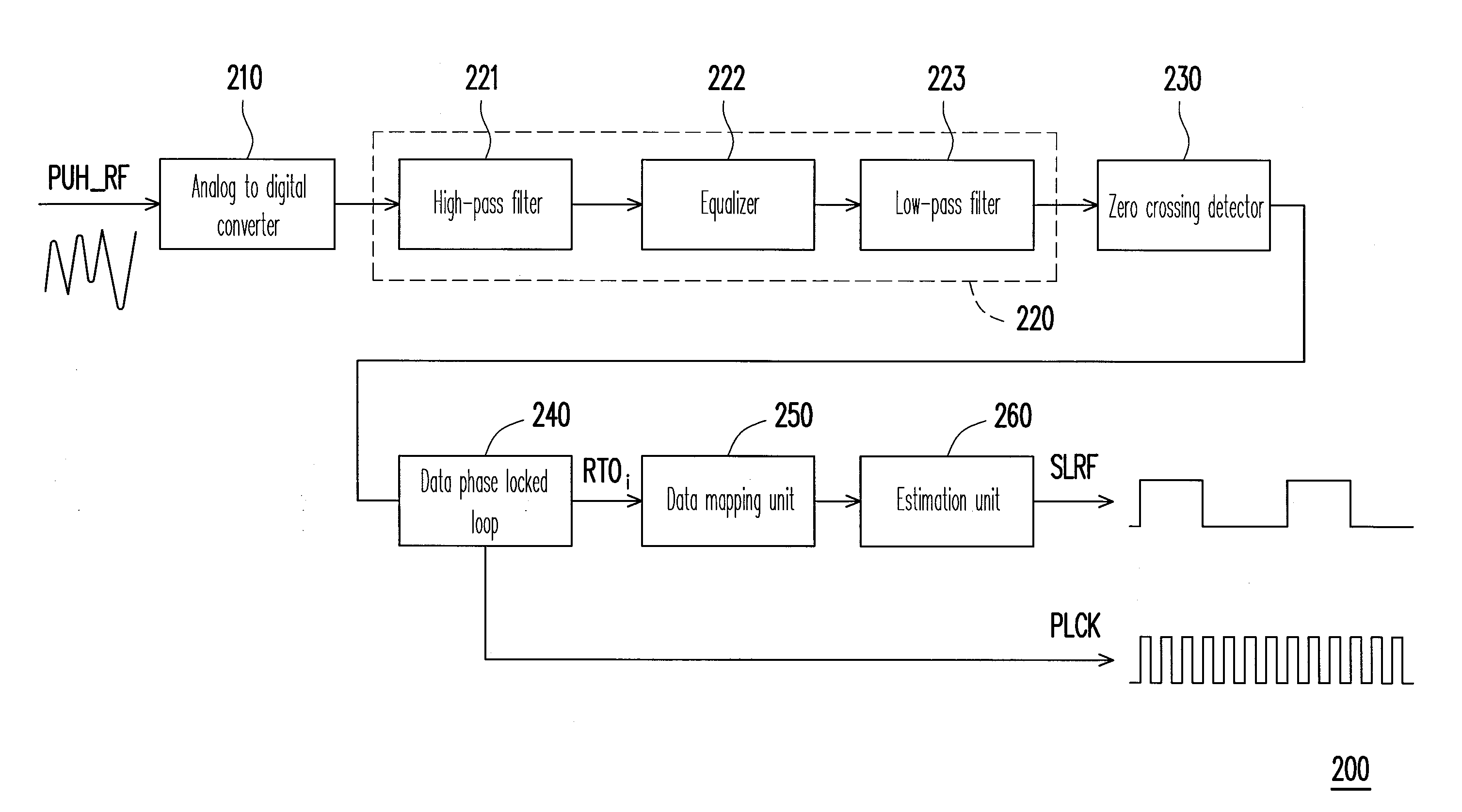
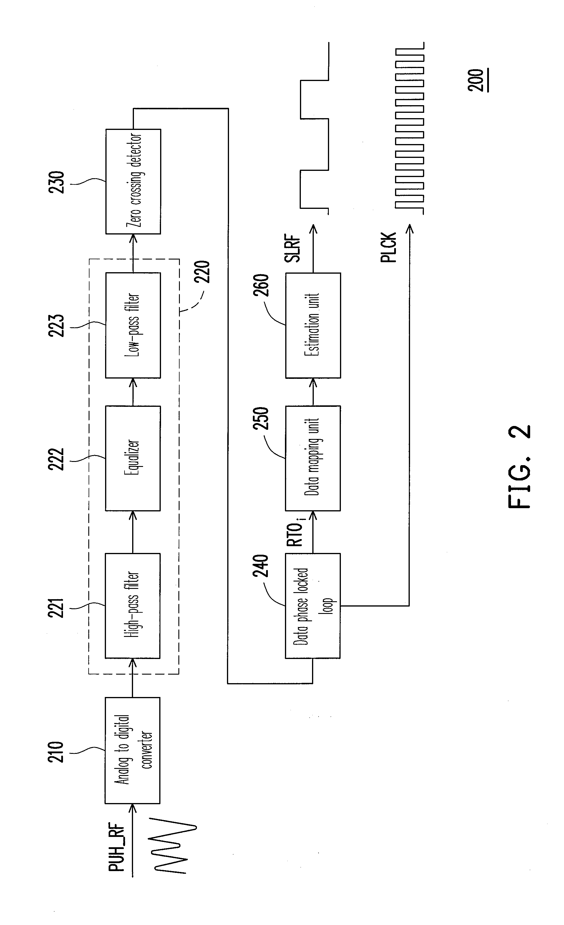
[0024]FIG. 2 is a block schematic diagram illustrating a data recovery device according to an embodiment of the invention. Referring to FIG. 2, the data recovery device 200 is used for recovering a radio frequency (RF) signal PUH_RF in an optical storage system to a clock signal PLCK and a modulation signal SLRF. In the present embodiment, the data recovery device 200 includes an analog to digital converter (ADC) 210, a filtering-equalizing unit 220, a zero crossing detector 230, a data phase locked loop 240, a data mapping unit 250 and an estimation unit 260. The filtering-equalizing unit 220 is coupled to the ADC 210. The zero crossing detector 230 is coupled to the filtering-equalizing unit 220. The data phase locked loop 240 is coupled to the zero crossing detector 230. The data mapping unit 250 is coupled to the data phase locked loop 240. The estimation unit 260 is coupled to the data mapping unit 250.

[0025]In view of a whole operation, the ADC 210 converts the RF signal PUH_R...


PUM


Abstract

A data recovery device including an analog to digital converter (ADC), a filtering-equalizing unit, a zero crossing detector, a data phase locked loop, a data mapping unit and an estimation unit is provided. The ADC converts a radio frequency signal to a plurality of sampling data points. The sampling data points are converted to a plurality of retiming data points and a clock signal by the filtering-equalizing unit, the zero crossing detector and the data phase locked loop. The data mapping unit selects a plurality of maximum data points and minimum data points from the returning data points, and determines whether to map the maximum data points and the minimum data points to other levels for partially reconstructing the retiming data points. The estimation unit recovers the reconstructed retiming data points to a modulation signal.

Description

CROSS-REFERENCE TO RELATED APPLICATION[0001]This application claims the priority benefit of Taiwan application serial no. 99132633, filed Sep. 27, 2010. The entirety of the above-mentioned patent application is hereby incorporated by reference herein and made a part of this specification.BACKGROUND[0002]1. Field of the Invention[0003]The invention relates to a data recovery device and method. Particularly, the invention relates to a data recovery device and method for an optical storage system.[0004]2. Description of Related Art[0005]When an optical storage system reads a radio frequency (RF) signal, it is liable to be influenced by factors such as inter-symbol interference (ISI), electrical delay, aging of dyes on a disc, or scratching surface of the disc to cause a poor recognition, so that a recognition degree of the RF signal is influenced. To avoid the above problem, the RF signal read by an optical pickup head has to be processed by a data recovery device, so that the system c...

Claims


Application Information

Patent Timeline
IPC IPC(8): G11B20/10G11B27/36
CPCG11B20/10055G11B20/1025G11B2220/2537G11B20/10314G11B20/10277
Inventor LIU, SHIH-HSIENCHEN, ZHIENG-CHUNG
Owner SUNPLUS TECH CO LTD
Learn More