Flow type particle image analysis method and device

Active Publication Date: 2012-03-29
HITACHI HIGH-TECH CORP
View PDF10 Cites 25 Cited by
  • Summary
  • Abstract
  • Description
  • Claims
  • Application Information

AI Technical Summary

Benefits of technology

[0022]According to the in-focus point adjustment method of the present invention, it is possible to accurately and efficiently perform in-focus point adjustment using standard particles of various particle

Problems solved by technology

Such microscopic tests have problems that the personnel's ability affects the results, the tests are time consuming, and so on, and are therefore desired to be made more efficient.
There are, however, cases where the shape of the flow of the sample liquid becomes thicker than a preset value due to

Method used


Image

  • Flow type particle image analysis method and device
  • Flow type particle image analysis method and device
  • Flow type particle image analysis method and device

Examples


Example

Embodiment 1

[0042]An embodiment of the present invention will be described below by using the drawings.

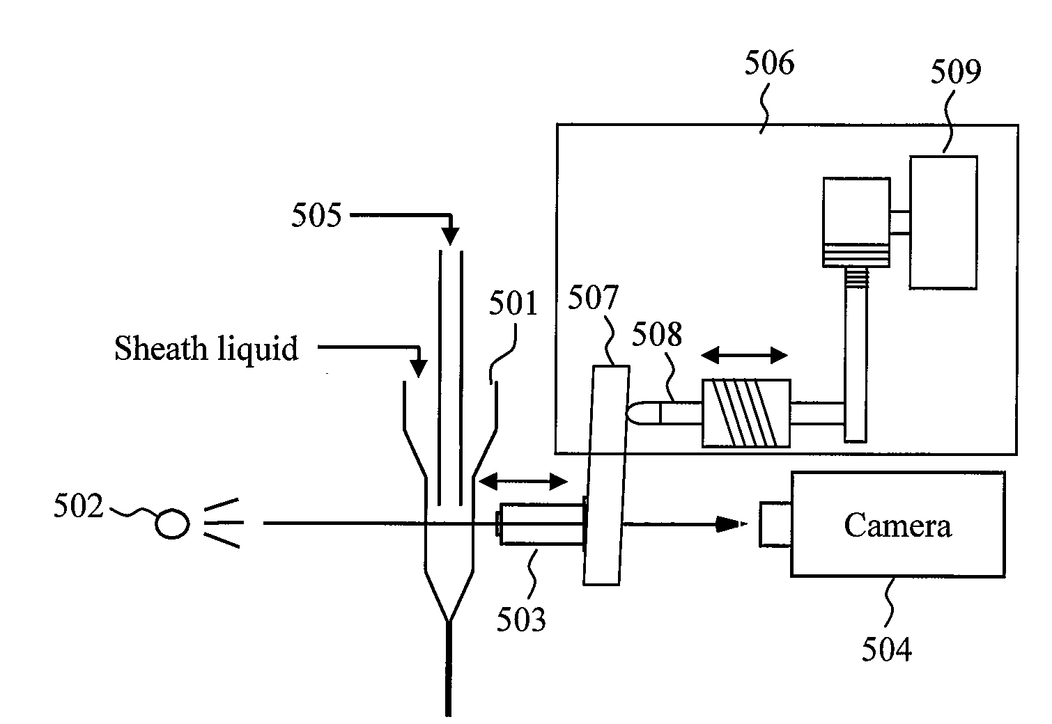
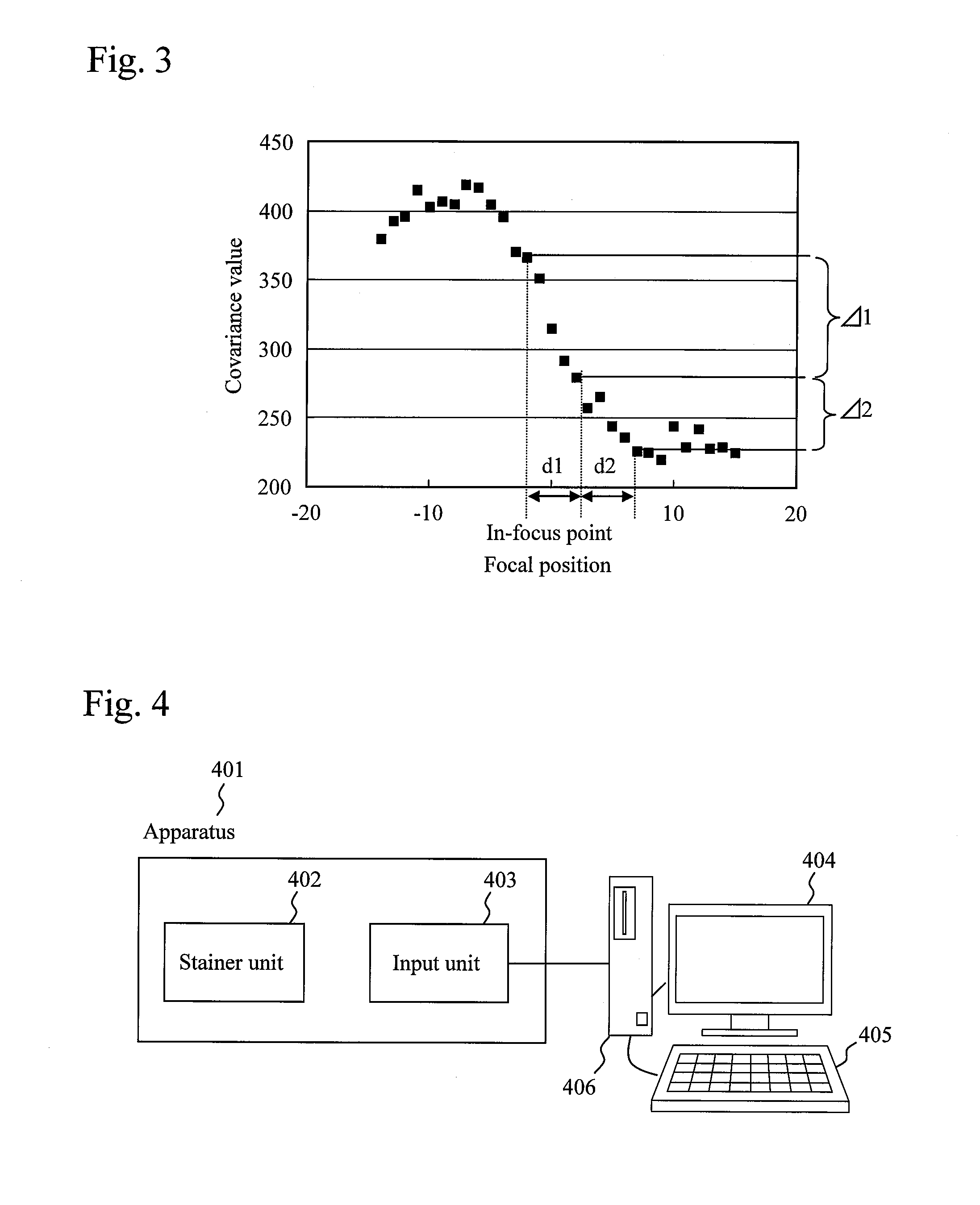
[0043]FIG. 4 is a diagram for describing an example of the configuration of a flow type particle image analysis device to which the present invention is applied. In an apparatus 401, a stainer unit 402 adds a stain to a sample, and after the elapse of a given period of time, an input unit 403 captures magnified static images of particles in the sample. The captured images are transferred to an image processing device 406, in which the particles in the samples are classified through image pattern recognition to count the types of particles contained in the sample of a single subject and also the frequency of appearance thereof. As the image processing device 406, a general-purpose personal computer including a display 404 and a keyboard 405 is used, for example. The counted results are reported to the operator through the display 404. A memory inside the image processing device 406 ...

Example

Embodiment 2

[0105]FIG. 18 is a diagram for describing an example of the configuration of a device for adjusting the in-focus point of a flow type particle image analysis device of the present invention and for checking the in-focus position and the thickness of the flow of a sample liquid.

[0106]In a case of in-focus point adjustment, standard particle images which are captured at multiple focal positions by an input device 1802 such as a camera are transferred to a memory 1801.

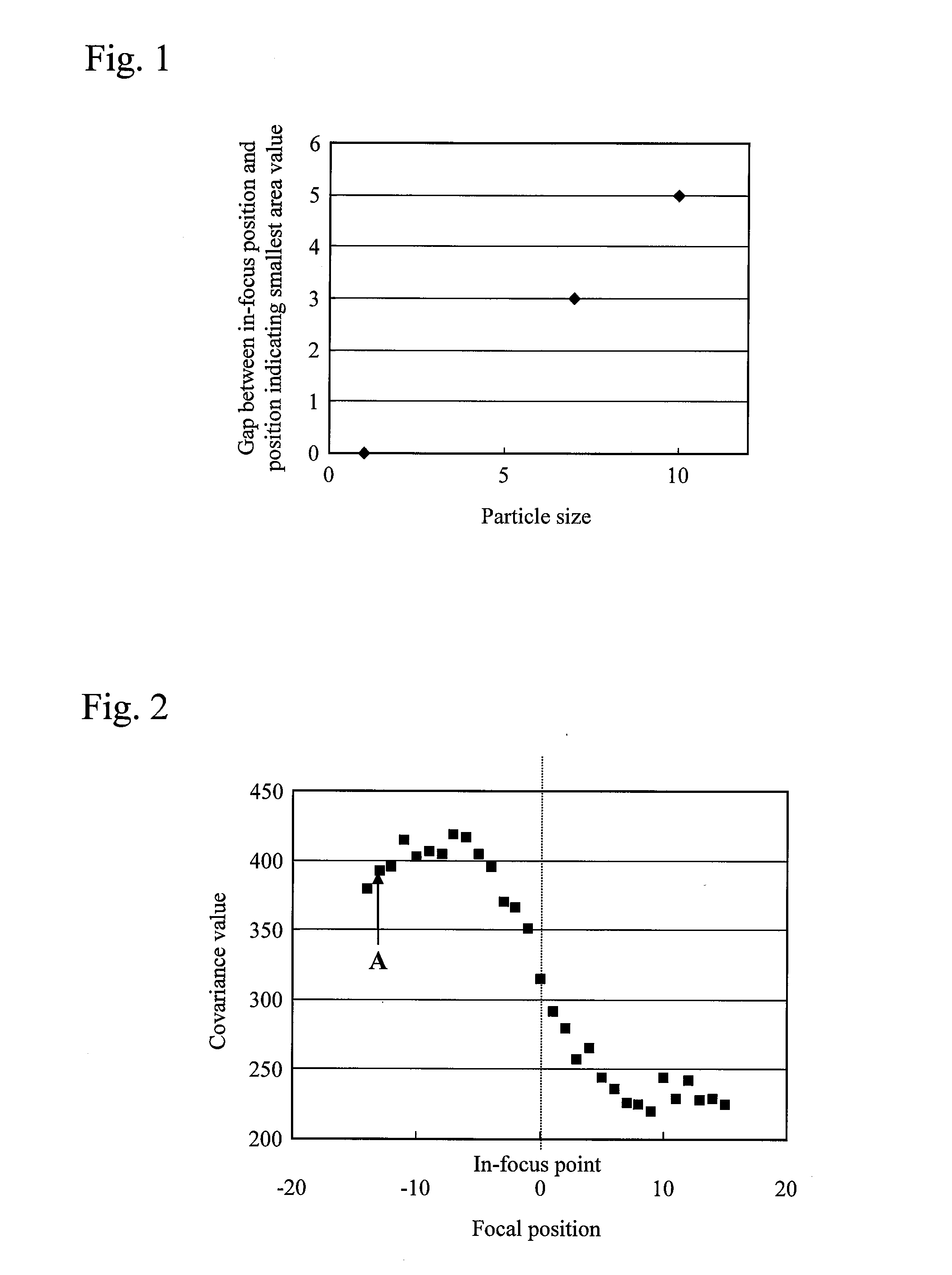
[0107]The standard particle images are then transferred to an image processing device 1803, in which region segmentation and calculation of feature parameters (area, focal adjustment parameter, etc.) are performed. For the methods of the region segmentation and the feature parameter calculation, the methods described in Embodiment 1 may be used.

[0108]Object region images obtained by the region segmentation and the feature parameters are transferred to the memory 1801.

[0109]The focal adjustment parameter of eac...


PUM


Abstract

At each of mutually different multiple focal positions, focal adjustment parameter values are obtained from images of standard particles made of the same substance. Each focal adjustment parameter value is figured out as any one of the ratio between the density value around the center of the standard particle image and the density value around the outline, the difference therebetween, and the density value around the center. The in-focus position is adjusted on the basis of the relationship between the obtained focal adjustment parameter values and the focal positions. Moreover, on the basis of the relationship between the focal adjustment parameter values and the focal positions, the parameter values are converted into focal positions, and the focal positions and dispersion thereof are used to check the displacement of the in-focus position and the thickness of the sample liquid.

Description

TECHNICAL FIELD[0001]The present invention relates to a flow type particle image analysis method and device for capturing an image of a particle in a flow cell and analyzing the static image of the particle.BACKGROUND ART[0002]In conventional particle image analyses, morphological tests on cells in blood and particles in urine are performed through a procedure in which a laboratory personnel prepares a sample on a microscope slide and directly observes it through a microscope. Such microscopic tests have problems that the personnel's ability affects the results, the tests are time consuming, and so on, and are therefore desired to be made more efficient.[0003]In recent years, with the advancement in automation of testing, Patent Documents 1 and 2, for example, have disclosed flow type particle image analysis devices in which: a sample is caused to flow through a flow cell having a special shape; particles in the sample are caused to flow through a wide imaging region; magnified imag...

Claims


Application Information

Patent Timeline
IPC IPC(8): G06K9/00
CPCG01N2015/1452G01N15/1459
Inventor MANRI, CHIHIROOOWADA, NORIOMITSUYAMA, SATOSHI
Owner HITACHI HIGH-TECH CORP
Why Eureka
Try Eureka