
System and method for biometric identification

Inactive Publication Date: 2012-03-29
KONINKLIJKE PHILIPS ELECTRONICS NV
View PDF13 Cites 5 Cited by
  • Summary
  • Abstract
  • Description
  • Claims
  • Application Information

AI Technical Summary

Benefits of technology

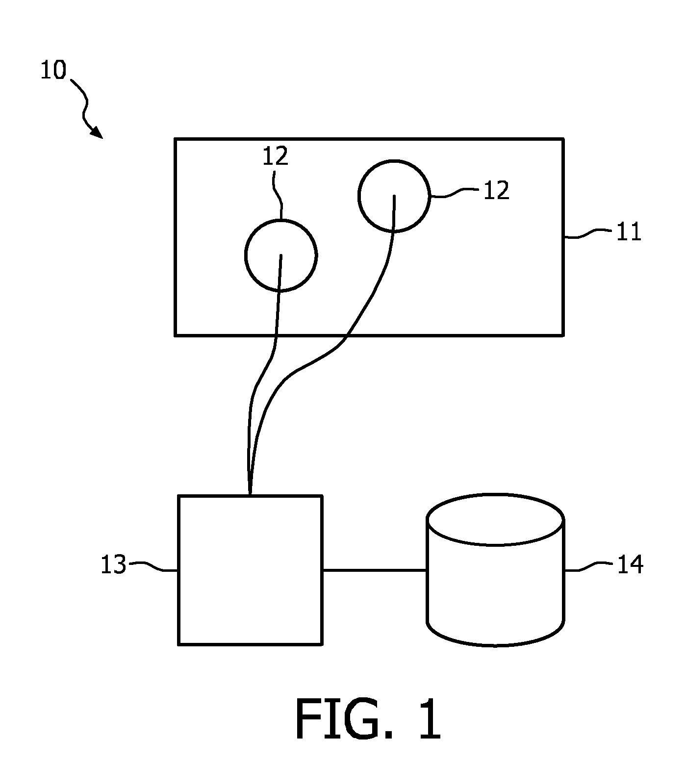
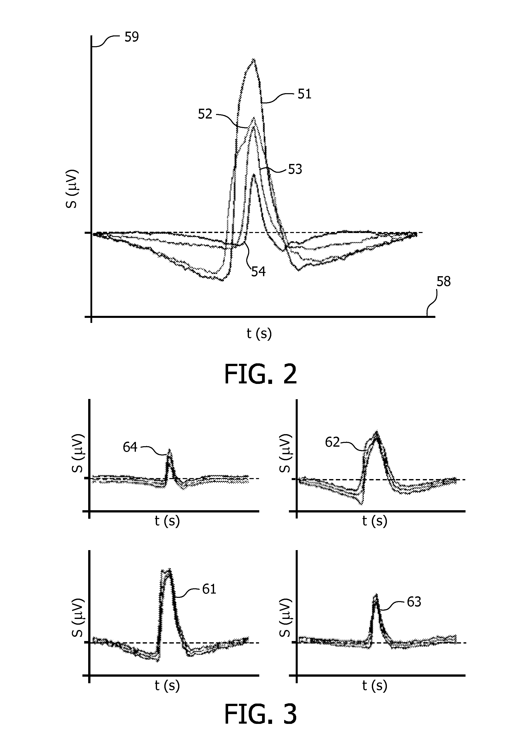
[0005]Eye blinking is an essential function of the eye that irrigates and removes irritants from the surface of the cornea. Several characteristics of the electrophysio logical signals obtained from the at least two electrodes and representing one or more eye blinks are user specific. Therefore, the comparison of the acquired eye blink characteristics with data in the database can be used for identification. Eye blink characteristics are independent of provided stimuli. It is an advantage of the system according to the invention, that no stimuli are required for performing the biometric identification. An adult person blinks, on average, 10 times a minute. Without supplying any stimulus, the system will still receive plenty of data for performing the biometric identification. The absence of stimulus providing means makes the system smaller and cheaper. The subject being identified is not hindered by any artificial stimulus needed for the identification. The system according to the invention thus is very easy to use and minimizes the amount of time and the effort the subject has to bear for being identified.

Problems solved by technology

Such measurement devices make it unnecessary to attach the multiple electrodes at correct positions on the users head separately.

Method used


Image

  • System and method for biometric identification
  • System and method for biometric identification
  • System and method for biometric identification

Examples


embodiment 21

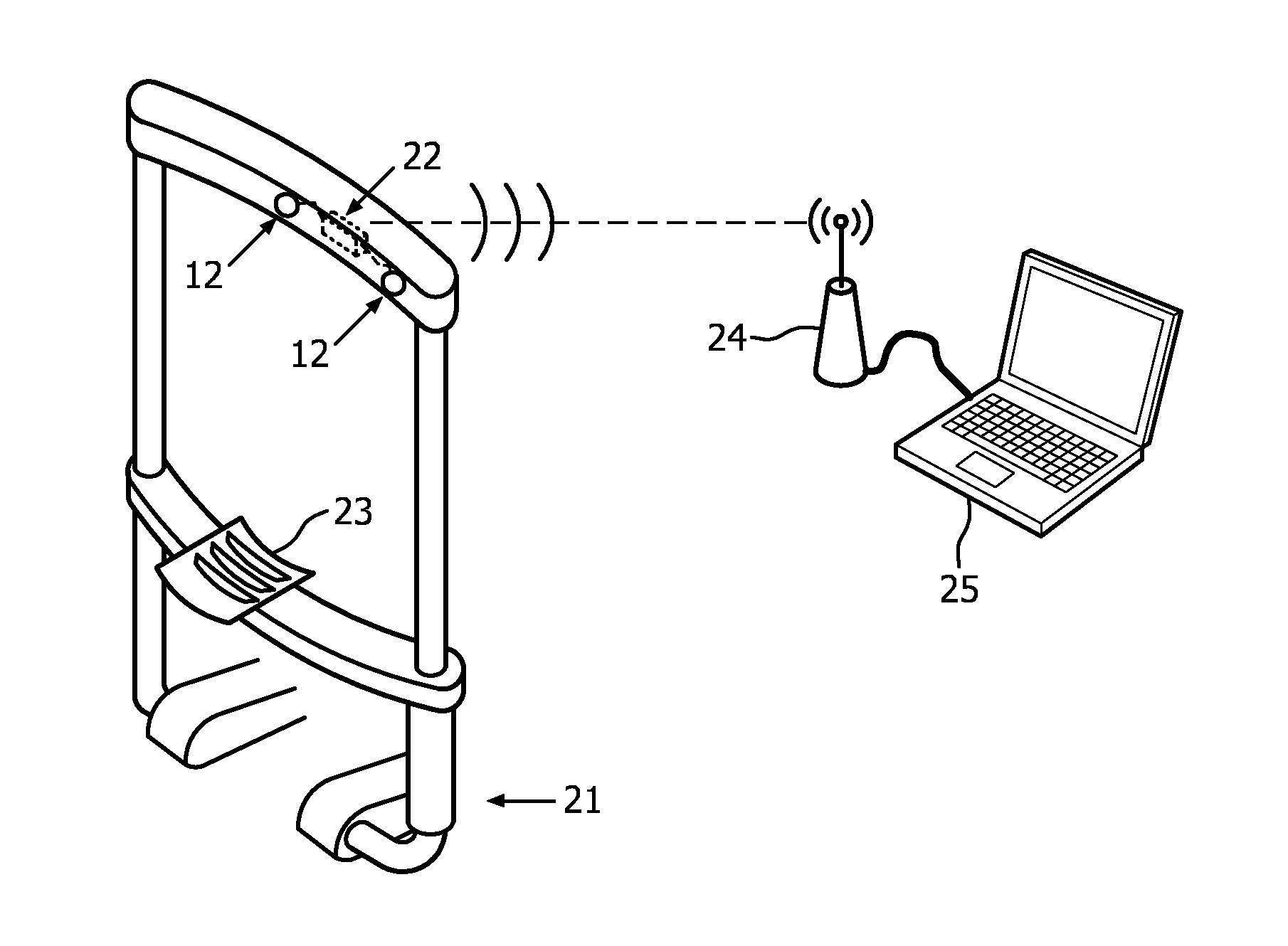
[0023]FIG. 4 shows a frame based embodiment 21 of the system according to the invention. This embodiment may, e.g., be used for deciding to grant a subject access to a certain room. The frame 21 may be installed next to a closed door. When the subject places his face against the frame 21, with his chin on the chin support 23, the electrodes 12 make contact with skin on the forehead of the user. The electrophysio logical signal captured by the electrodes 12 during at least one eye blink are sent to a nearby receiver 24 by a transmitter 22 integrated in the frame 21. The receiver is coupled to a computer 25 which comprises the processor 13 for comparing the captured data to the stored data. The stored eye blink characteristics may be in a database 14 comprised in the computer 25. Alternatively, the computer 25 is coupled to the database 14 via a local or wide area network. If the subject is recognized as an authorized person, the door is unlocked or opened.

embodiment 31

[0024]FIG. 5 shows a helmet based embodiment 31 of the system according to the invention. This helmet 31 may, e.g., be used in computer games or virtual reality applications. The helmet 31 comprises two or more electrodes 12 which make contact with the forehead of the subject when the helmet is worn and used for biometric identification. The processor 13 and the database 14 may be comprised in one or more electronics compartments 32 in the helmet 31. Preferably, the helmet 31 only comprises a transmitter or transmitter / receiver for sending the captured electrophysiological signals to a nearby computer with a receiver. The electronics compartment 32 may further comprise a battery for powering the electrodes, the transmitter or other electronic equipment.

[0025]In other embodiments, the electrodes may, e.g., be integrated in a pair of glasses or a headband.

[0026]FIG. 6 shows a flow diagram of the method according to the invention. The figure shows a four step method. As already elucida...


PUM


Abstract

A system (10) is provided for enabling biometric identification. The system (10) comprises at least two electrodes (12), a database (14) and a processor (13). The at least two electrodes (12) are to be applied to a face of a subject for capturing electrophysiological signals (51, 52, 53, 54) therefrom. The subject is one of the registered users. The database (14) comprises characteristic eye blink data of registered users. The processor (13) is operably coupled to the electrodes (12) and the database (14) and is operative to receive the electrophysiological signals (51, 52, 53, 54) from the at least two electrodes (12) during at least one eye blink of the subject, to derive eye blink characteristics from the obtained electrophysiological signals (51, 52, 53 54), to make a comparison of the derived eye blink characteristics with at least part of the characteristic eye blink data in the database (14) and to determine an identity of the subject, based on the comparison.

Description

FIELD OF THE INVENTION[0001]This invention relates to a system for biometric identification, a device, a method and a computer program product for biometric identification.BACKGROUND OF THE INVENTION[0002]A biometric identification system is described in United States patent application US 2008 / 0104415 A1. In that patent application, an apparatus is described for recognizing a subject based on biometric features. The apparatus first selects at least one stimulus from a database and provides the stimulus to the subject. Then the device uses at least one sensor to acquire a response of the subject to the stimulus. The response is analyzed and compared to pre-stored subject specific identification templates for recognizing the object. The acquired responses may be physical, physiological or behavioral. Three sub systems for detecting the responses are described in patent application US 2008 / 0104415. One sub system uses a video camera. Another sub system uses electro-oculography. The la...

Claims


Application Information

Patent Timeline
IPC IPC(8): G06K9/00
CPCG06K9/00597G06K9/0053G06F18/00G06F2218/10G06V40/18
Inventor GARCIA MOLINA, GARY NELSONMIHAJLOVIC, VOJKANERKENS, IVO JOHANNES MARIAHUSEN, SRI ANDARI
Owner KONINKLIJKE PHILIPS ELECTRONICS NV
Learn More