Horizontal Axis Logarithmic Spiral Fluid Turbine

a fluid turbine and logarithmic spiral technology, applied in the field of turbines, can solve the problems of increasing the cost and decreasing the supply of fossil fuels, the need to build costly the need to build damns and structures to control the flow direction and speed of water current, so as to achieve the effect of efficiently collecting fluid kinetic energy

Inactive Publication Date: 2012-03-29
ABASS OMAR NABIL
View PDF11 Cites 33 Cited by
  • Summary
  • Abstract
  • Description
  • Claims
  • Application Information

AI Technical Summary

Benefits of technology

[0016]One objective of the present invention is to guide the moving fluid around the logarithmic turbine's rotary axle and between the blades in a manner to collect the fluid kinetic energy more efficiently than in prior arts.

Problems solved by technology

The rising cost and decreasing supply of fossil fuels creates a considerable need in harnessing renewable energy such as flowing wind and water more efficiently.
For example, water mills that are currently used to generate electric power require a considerable quantity of strong water current to operate efficiently resulting in a need to build costly damns and structures to control the water current flow direction and speed.
Presently, wind turbines not only compromise a significant amount of their torque to acquire high speed, but also require a relatively big space and in some cases, they may even be hazardous.
Also, they are known to be expensive to construct, maintain, and engineer.

Method used


Image

  • Horizontal Axis Logarithmic Spiral Fluid Turbine
  • Horizontal Axis Logarithmic Spiral Fluid Turbine
  • Horizontal Axis Logarithmic Spiral Fluid Turbine

Examples


Embodiment Construction

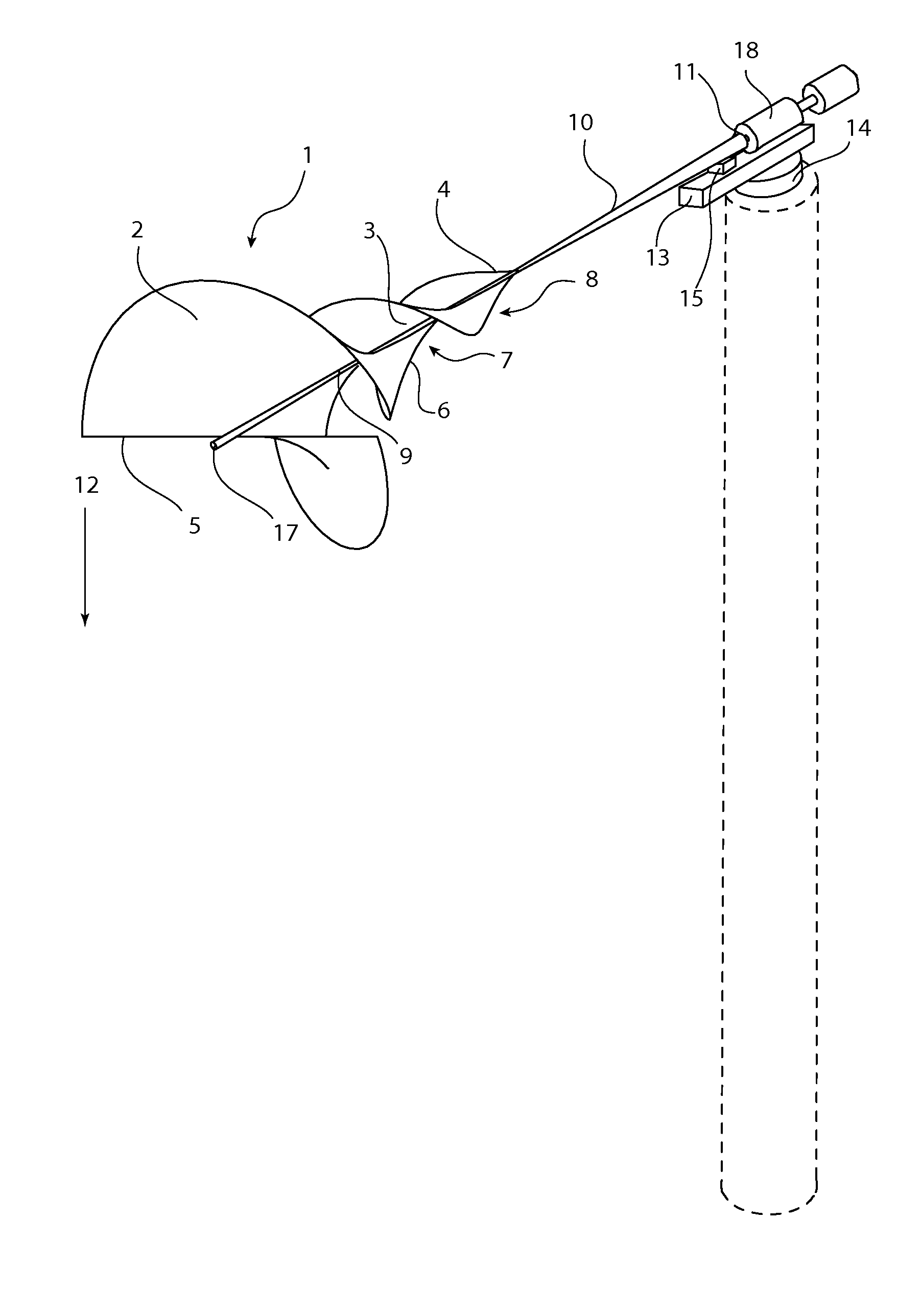
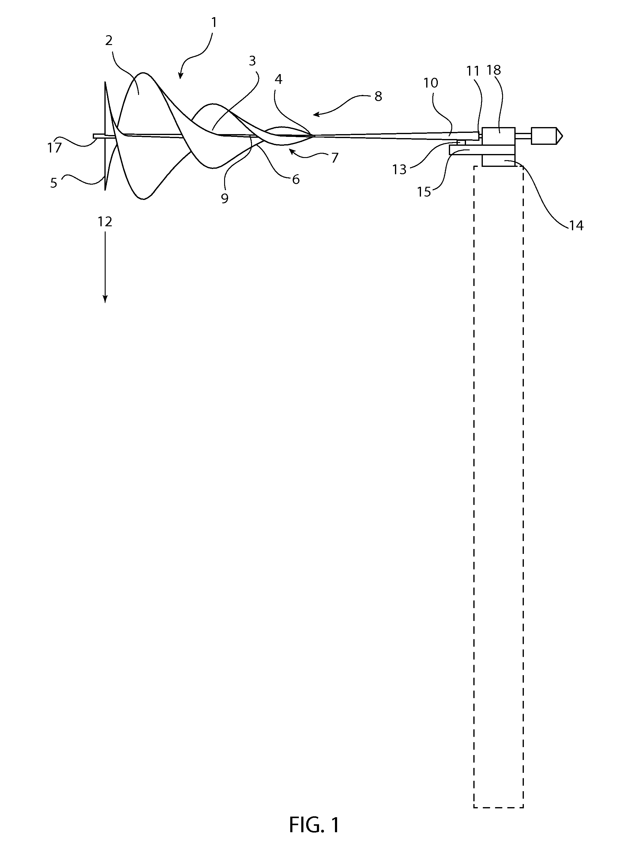
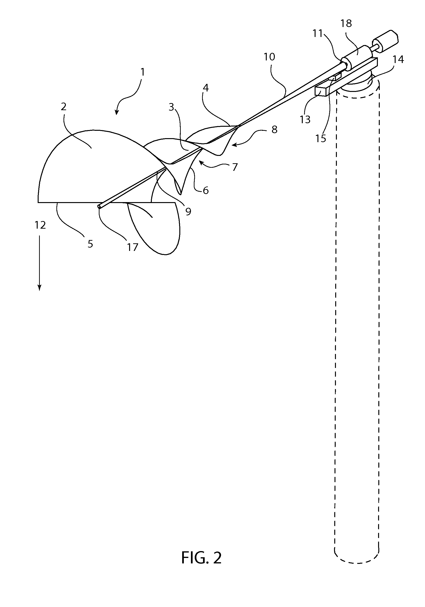
[0024]All illustrations of the drawings are for the purpose of describing selected versions of the present invention and are not intended to limit the scope of the present invention.

[0025]Of the many possible functions of the horizontal axis logarithmic spiral fluid turbine, otherwise known as a logarithmic turbine, one is to transform rotational energy into electric power by rotating an electric generator. This use demonstrates the ability to provide electricity that can be used for a variety of different uses. Another use for the logarithmic turbine is for it to be installed on a fixed tower facing the wind or water flow to generate electric power. It could have a self orientation mechanism to face the current if front is attached by a pivoting bearing to a vertical tower. Also it may be installed on a fast moving object to generate power from relative fluid flow. For example, the logarithmic turbine may be pulled behind a boat or mounted on a vehicle to generate power when object...


PUM


Abstract

The present invention is a more simplified and efficient design of a turbine. The use of a logarithmic curve pattern for blade design and an aerodynamic profile allows the present invention to not only be versatile in its uses, but also much more efficient at gathering forms of energy for different purposes.

Description

[0001]The current application claims a priority to the U.S. Provisional Patent application Ser. No. 61 / 387,894 filed on Sep. 29, 2010.FIELD OF THE INVENTION[0002]The present invention relates generally to turbine for the generation of electrical energy. More specifically, the present invention takes the shape of a logarithmic spiral with a horizontal axis for efficient rotation. The present invention relates to fluid rotors, also called turbines, and pertains particularly to a rotor for flowing water, wind and the like.PRIOR ART[0003]In the World International Patent Organization Application 2010043887A2, the process of attaining vortical flow is achieved using two components involving a turbine mounted to a duct with guide vanes to channel the fluid and change its direction and speed before contact with the said turbine. Thus, the uniqueness and efficiency of this design lies in the presence of the two components together. This turbine works only if facing the fluid current directi...

Claims


Application Information

Patent Timeline
Patent Type & Authority Applications(United States)
IPC IPC(8): F01D5/14
CPCF03B3/121F05B2200/23F03D1/0625F05B2220/32F05B2240/21F05B2240/221F05B2240/911F05B2240/97F05B2250/15F05B2250/25Y02E10/223Y02E10/28Y02E10/721Y02E10/728F03B17/061Y02E10/20Y02E10/30Y02E10/72
Inventor ABASS, OMAR NABIL
Owner ABASS OMAR NABIL
Why Eureka
Try Eureka