In-situ battery diagnosis method using electrochemical impedance spectroscopy

a technology of impedance spectroscopy and in-situ battery, which is applied in the direction of electrical testing, instruments, electric digital data processing, etc., can solve the problems of soc estimation errors, dependencies are in reality much more complicated, and estimation errors

Inactive Publication Date: 2012-03-29
INST FR DU PETROLE
View PDF2 Cites 48 Cited by
  • Summary
  • Abstract
  • Description
  • Claims
  • Application Information

AI Technical Summary

Problems solved by technology

These methods however lead to estimation errors by disregarding phenomena such as self-discharge.
However, these dependencies are in reality much more complicated than what is normally taken into account in the BMS, which often leads to SoC estimation errors.
This method however requires much instrumentation, notably for inserting a reference electrode in the element, and more complex electronic management of the battery.
However, this method is more difficult to implement for Li-ion type elements whose response variations after this type of perturbation are very low and can therefore not allow precise SoH measurement.

Method used


Image

  • In-situ battery diagnosis method using electrochemical impedance spectroscopy
  • In-situ battery diagnosis method using electrochemical impedance spectroscopy
  • In-situ battery diagnosis method using electrochemical impedance spectroscopy

Examples


example 1

Case of an Element of Chemical Composition LFP / C

[0103]Stage 1

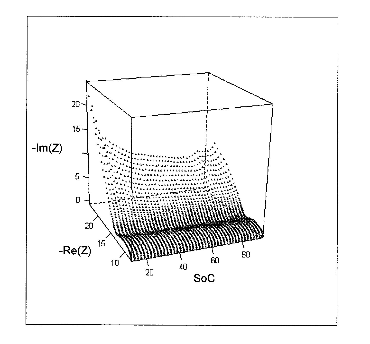
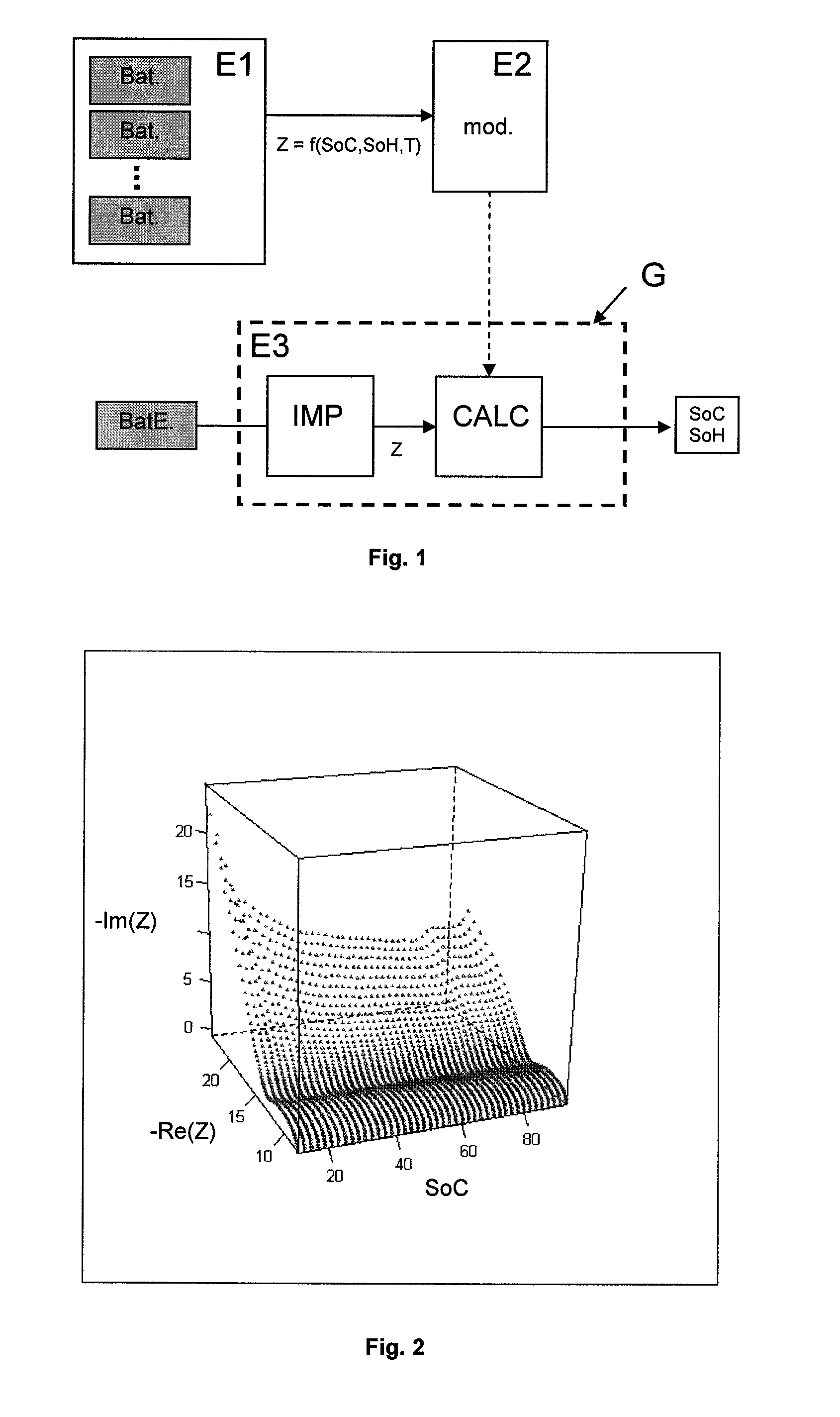
[0104]FIG. 6 illustrates a Bode diagram wherein ω represents the frequency in Hz, P represents the phase in degrees and Z represents the electrochemical impedance modulus in Ohm. This diagram allows to compare the impedances determined for several states of charge on a C / LFP type battery. These impedances were obtained using successively sinusoidal signals of different frequencies. The impedances can also be obtained differently, for example by superposing a white noise on the battery charge / discharge signals.

[0105]It can be noted that, in the diagram, the impedances are not superimposed and that they evolve as a function of the charged capacity.

[0106]Stage 2

[0107]These differences are quantified according to the invention by adjusting an impedance model on the curves of the impedance diagram by means of the formula as follows:

Z(ω,SoC)=a**ω+b+1c1+d1**ωn1+1c2+d2**ωn2

where a, b, c1, d1, n1, c2, d2, n2 are parameters to be ad...

example 2

Case of an Element of Chemical Composition NCO / C

[0114]This new example allows to test the robustness of the method according to the invention for various battery technologies. The impedance diagram (Nyquist diagram) with 50% SoC of the NCO / C technology is shown in FIG. 9. The shape of this curve suggests the convolution of 3 semi-circles, which allows to define the model as follows:

Z(ω,SoC)=a**ω+b+1c1+d1**ωn1+1c2+d2**ωn2+1c3+d3**ωn3

where a, b, c1, d1, n1, c2, d2, n2, c3, d3, n3 are parameters to be adjusted according to the experimental values.

[0115]By proceeding as in the previous example, this model is adjusted on the impedance diagrams as a function of the frequency, the state of charge and the temperature, and it leads to an impedance model as a function of the SoC, the temperature and the frequency.

[0116]Using another element of identical chemical composition, of known SoC, and the previous model, it is possible to calculate the SoC of this element from a determination of its e...


PUM

PropertyMeasurementUnit
temperatureaaaaaaaaaa
electrochemical impedance measurementsaaaaaaaaaa
electrochemical impedanceaaaaaaaaaa

Abstract

Method of estimating the internal state of an electrochemical system for electric power storage, such as a battery.The SoC and the electrochemical impedance are determined for various internal states of an electrochemical system of the same type as the electrochemical system studied. An electrochemical impedance model is then defined as a function of the SoC and of parameters. These parameters are calibrated through adjustment on the electrochemical impedance measurements obtained for the various internal states. The electrochemical impedance Z of the system studied is determined and its SoC is estimated using the model applied to electrochemical impedance Z.

Description

FIELD OF THE INVENTION[0001]The present invention relates to a method of estimating the internal state of an electrochemical system for electric power storage, such as a battery (lead, Ni-MH, Li-ion, etc.). The method allows to manage batteries used in stationary or on-board applications, notably during the operation thereof.[0002]The battery is one of the most critical components in the case of hybrid or electric vehicle applications. Proper operation of these applications is based on a smart battery management system (BMS) whose purpose is to operate the battery with the best compromise between the various dynamic demand levels. This BMS requires precise and reliable knowledge of the state of charge (SoC) and of the state of health (SoH).[0003]The state of charge (SoC) of a battery corresponds to its available capacity and it is expressed in percentage of its nominal capacity given by the manufacturer, or in percentage of its total capacity measured under given conditions when suc...

Claims


Application Information

Patent Timeline
Patent Type & Authority Applications(United States)
IPC IPC(8): G06F19/00G01N27/416
CPCG01R31/3662G01R31/3651G01R31/389G01R31/367
Inventor MINGANT, REMYBERNARD, JULIENSAUVANT-MOYNOT, VALERIE
Owner INST FR DU PETROLE
Why Eureka
Try Eureka