Clothes treating apparatus and operating method thereof

a technology for treating apparatus and clothes, which is applied in the direction of drying machines, lighting and heating apparatus, furnaces, etc., can solve the problems of lowering reducing the reliability of products, and reducing the thermal efficiency, so as to enhance the reliability of clothes treating apparatus, improve energy efficiency, and facilitate inspection.

Active Publication Date: 2012-04-05
LG ELECTRONICS INC
View PDF3 Cites 4 Cited by
  • Summary
  • Abstract
  • Description
  • Claims
  • Application Information

AI Technical Summary

Benefits of technology

[0011]Therefore, an object of the present invention is to provide a method capable of rapidly and easily detecting whether an auxiliary fan normally operates or not in a clothes treating apparatus with a heat pump system.
[0012]Another object of the present invention is to provide a clothes treating apparatus having a detecting means for rapidly and easily detecting whether an auxiliary fan normally operates or not.
[0025]In the present invention, whether the auxiliary fan operates or not may be rapidly and easily checked without a user's naked eyes. This may enhance the reliability of the clothes treating apparatus, and improve the energy efficiency.

Problems solved by technology

Here, the air may have the loss of its thermal energy while being cooled.
However, the thermal energy is exhausted to the outside, resulting in lowering of the thermal efficiency.
If heat exchange is not smoothly performed at the condenser due to an abnormal state of the auxiliary fan, a refrigerant is overheated to lower the reliability of the product.
Furthermore, the amount of power consumption by the compressor is increased due to an overload applied to the compressor.
This may lower the energy efficiency.
However, this is difficult since a user cannot easily access to a position where the auxiliary fan is installed, and cannot easily check with his or her naked eyes.
This may cause a user to have a difficulty in checking an abnormal state of the auxiliary fan from the outside.

Method used


Image

  • Clothes treating apparatus and operating method thereof
  • Clothes treating apparatus and operating method thereof
  • Clothes treating apparatus and operating method thereof

Examples


Embodiment Construction

[0030]Reference will now be made in detail to the preferred embodiments of the present invention, examples of which are illustrated in the accompanying drawings. It will also be apparent to those skilled in the art that various modifications and variations can be made in the present invention without departing from the spirit or scope of the invention. Thus, it is intended that the present invention cover modifications and variations of this invention provided they come within the scope of the appended claims and their equivalents.

[0031]Description will now be given in detail of a drain device and a refrigerator having the same according to an embodiment, with reference to the accompanying drawings.

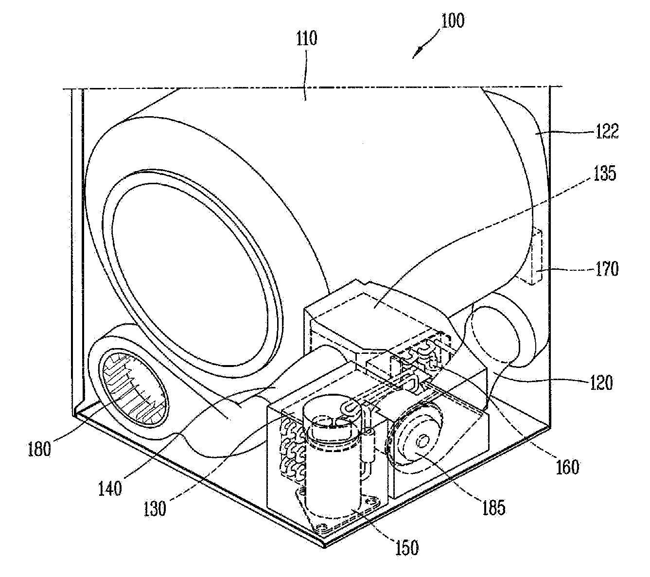
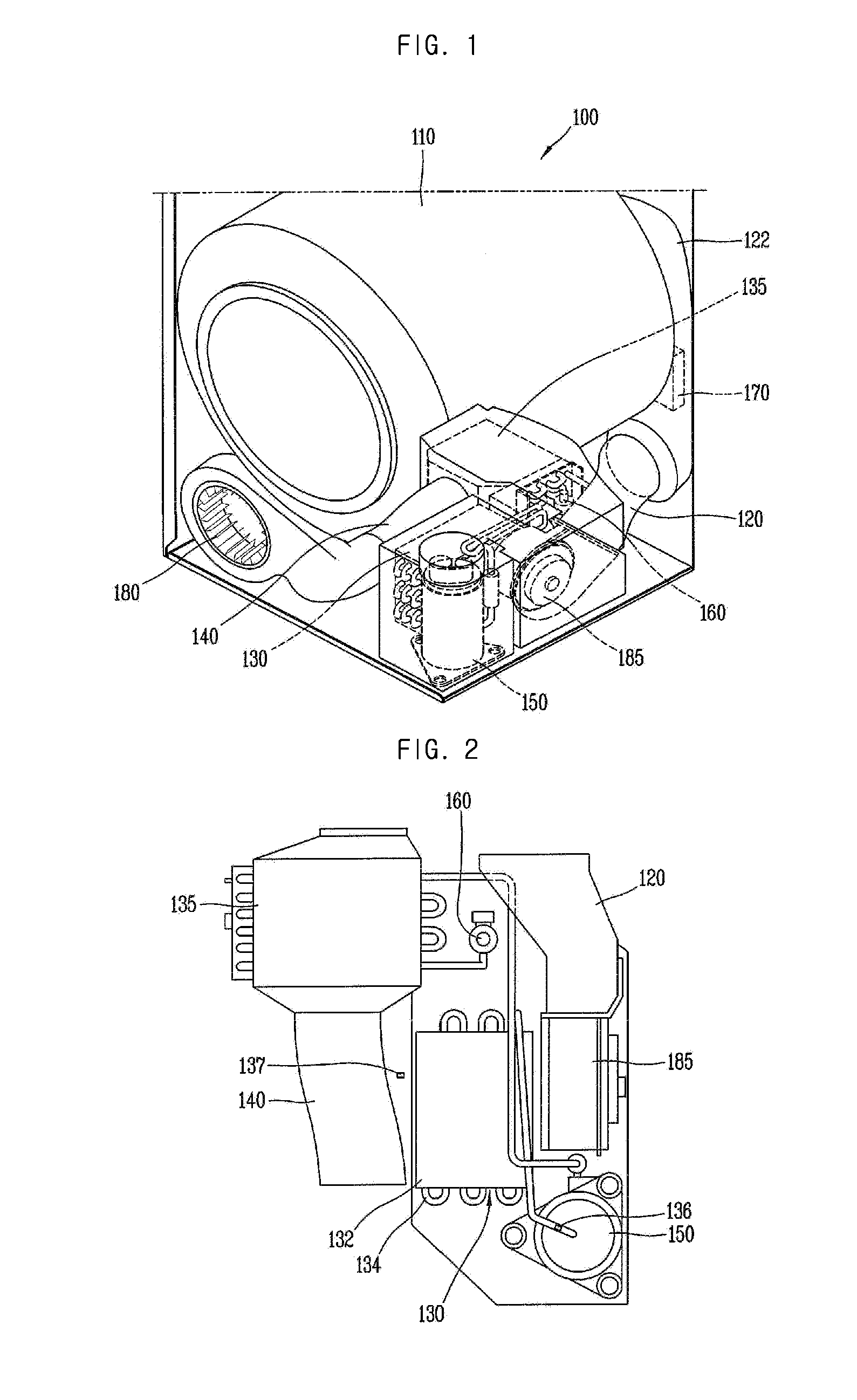
[0032]Hereinafter, with reference to the attached drawings, will be explained a clothes treating apparatus having a heat pump system, and an operating method thereof.

[0033]FIG. 1 is a perspective view schematically illustrating an inner structure of a clothes treating apparatus according ...


PUM


Abstract

A clothes treating apparatus including a drum, an air suction duct forming a flow path of air introduced into the drum, an auxiliary fan introducing air into the air suction duct, an air exhaustion duct forming a flow path of air exhausted from the drum, a main fan exhausting air to the air exhaustion duct from the drum, a condenser heating air sucked into the drum through the air suction duct, an evaporator cooling air exhausted from the drum through the air exhaustion duct, and a compressor and an expander forming a heat pump together with the condenser and the evaporator. The method includes measuring a discharge side pressure of the compressor, and comparing the measured discharge side pressure with a maximum allowable pressure, and determining that the auxiliary fan does not operate when the discharge side pressure is more than the maximum allowable pressure.

Description

TECHNICAL FIELD[0001]The present invention relates to a clothes treating apparatus and an operating method thereof, and more particularly, to a clothes treating apparatus having a heat pump system, and a method for checking whether an auxiliary fan configured to supply air into a drum of the clothes treating apparatus is in an abnormal state.BACKGROUND ART[0002]Generally, a clothes treating apparatus having a drying function, such as a washing machine or a clothes dryer, serves to dry laundry having been completely washed and dehydrated, by introducing the laundry into a drum, by supplying hot blast into the drum, and then by evaporating moisture from the laundry.[0003]Hereinafter, the clothes treating apparatus will be explained with taking a clothes dryer as an example. The clothes dryer includes a drum rotatably installed in a body and having laundry introduced thereinto, a driving motor configured to drive the drum, a blowing fan configured to blow air into the drum, and a heati...

Claims


Application Information

Patent Timeline
Patent Type & Authority Applications(United States)
IPC IPC(8): F26B21/12F26B3/02
CPCD06F58/206F26B23/005D06F2058/287D06F58/28D06F37/42D06F58/02D06F58/50D06F2103/36D06F2103/50D06F2103/54D06F2103/58D06F2105/24D06F2105/26D06F2105/30
Inventor LEE, HYUKSOOYE, SUNGMINKIM, SEONGHWAN
Owner LG ELECTRONICS INC
Why Eureka
Try Eureka