
Method and Apparatus for Quality Control and Quality Assurance of Sized Bridging Materials Used in Drill-In Fluid Formulation

a technology of bridging materials and fluid formulations, applied in the field of drill-in fluids, can solve the problems of severe formation damage, fragmentation of product quality, and damage to wellbores, and achieve the effect of minimizing formation damag

Active Publication Date: 2012-04-05
SAUDI ARABIAN OIL CO
View PDF4 Cites 9 Cited by
  • Summary
  • Abstract
  • Description
  • Claims
  • Application Information

AI Technical Summary

Benefits of technology

The patent text describes a method and apparatus for testing and quantifying the durability of bridging materials used in drill-in fluids for oil and gas drilling operations. The method involves sieving the bridging materials to create uniform batches and selecting a primary uniform batch to remove residual moisture. The method can provide a simple and reliable way to evaluate the durability of bridging materials and minimize formation damage during drilling operations. The invention can also account for factors that play a significant role in the wet grinding process and provide an aggressive wet grinding test to reflect the "worst ease" scenario in the downhole environment. The method can be performed in a laboratory-based or field-deployable apparatus and method, requiring no special skill or experience. Overall, the invention provides a tool for selecting the best bridging material to prevent formation damage while drilling.

Problems solved by technology

These sized mud additives, however, are manufactured by using various grinding procedures and equipment and result in divergent product quality.
Applicants further recognize that, although properly sized bridging materials are useful in plugging and sealing fractures and openings of borehole walls to create a tight and low-permeable mudcake, failure to maintain the intended particle size distribution may be a severe cause of near wellbore formation damage while drilling.
Applicants further recognize that failure to monitor the changes in particle size distribution and lack of any remedial action to correct it may lead to severe formation damage as a result of reduction of the median particle size of the bridging materials due to crushing and grinding action of the down hole tools and equipment.
Applicants also recognize the instability in particle size distribution arises due to the easy disintegration and dispersion of poor quality bridging materials in down hole conditions due to the physical interactions with a drill bit, tool joint, reamer, stabilizer, mud motor stator and blades, bend drill string in case of horizontal, extended reach, and multilateral drilling operations—producing a dramatic change in the PSD, PSD curve, and particle size cut points.

Method used


Image

  • Method and Apparatus for Quality Control and Quality Assurance of Sized Bridging Materials Used in Drill-In Fluid Formulation
  • Method and Apparatus for Quality Control and Quality Assurance of Sized Bridging Materials Used in Drill-In Fluid Formulation
  • Method and Apparatus for Quality Control and Quality Assurance of Sized Bridging Materials Used in Drill-In Fluid Formulation

Examples


Embodiment Construction

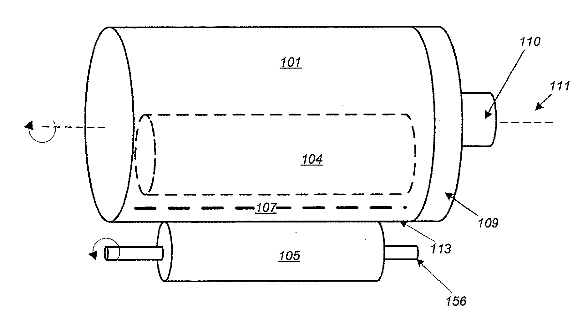
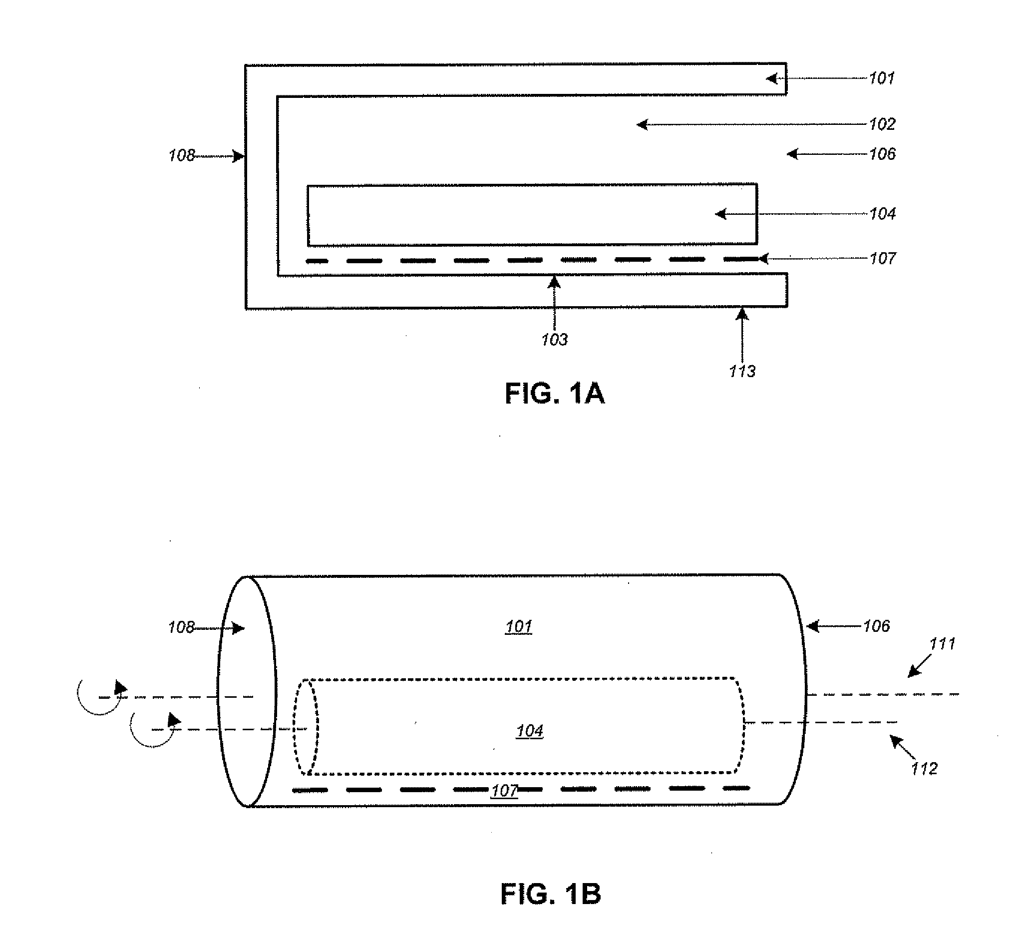
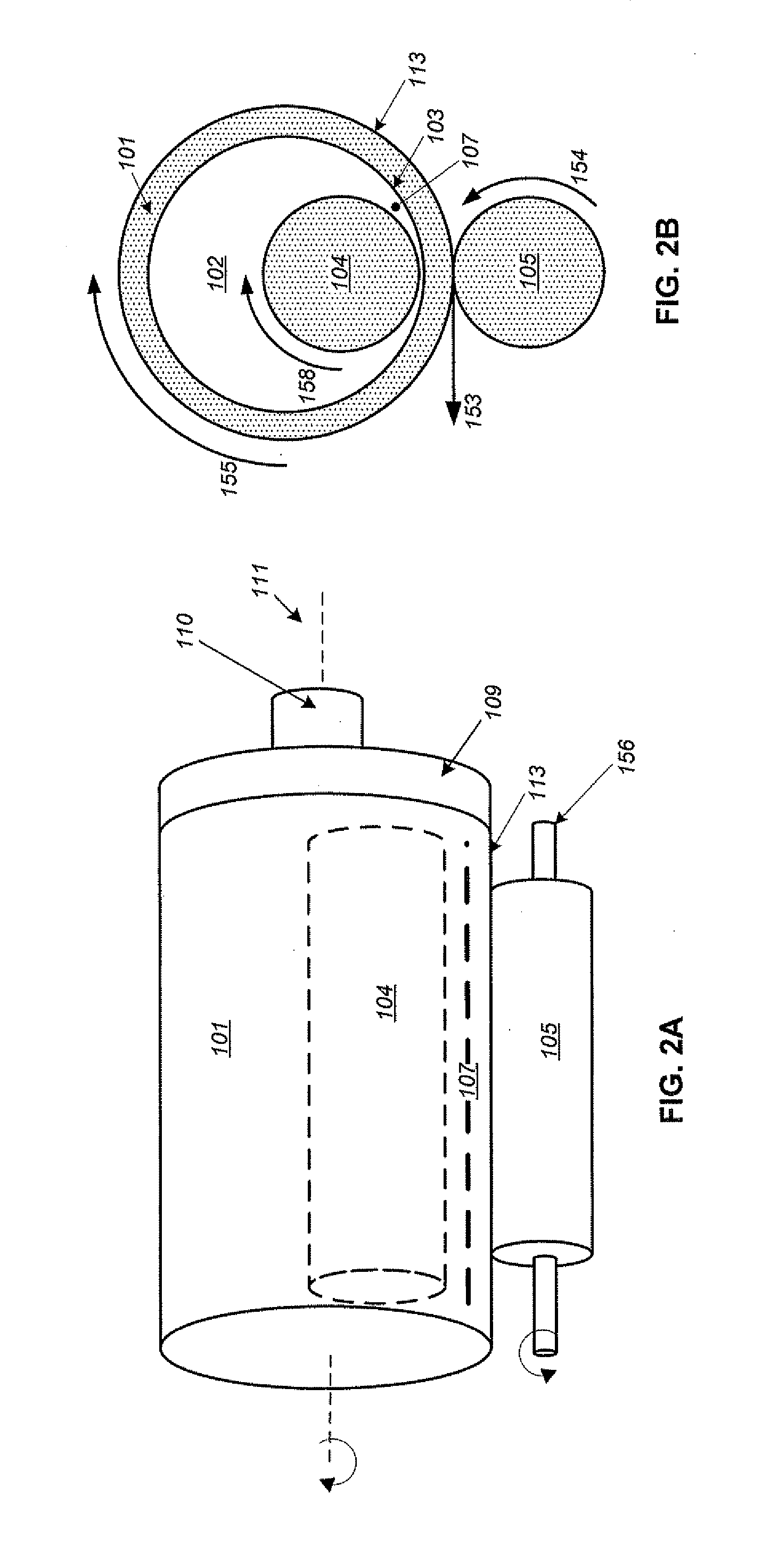
[0044]Embodiments of the present invention include an apparatus for testing structural durability characteristics of sized bridging materials by simulating downhole tool interactions and wet grinding actions upon sized bridging materials. The apparatus 100 can be shown with reference to FIG. 1A, FIG. 1B, FIG. 2A, and FIG. 2A. The apparatus 100 includes a cylindrical tubular container 101 having an outer surface 101 that is substantially cylindrically shaped. As can be shown with reference to the cross-section of FIG, 1A, the tubular container 101 is hollow, and the open space 102 within the tubular container 101 is bound by an inner surface 103 of the tubular container. The inner space 102 of the tubular container 101 is also of a substantially cylindrical shape, and is defined herein as a testing cell 102.

[0045]The tubular container 101 also has two ends 108 and 106 that correspond to bases of the cylindrical shape of the tubular container 101. A major axis 111 of the tubular conta...


PUM

PropertyMeasurementUnit
volumeaaaaaaaaaa
massaaaaaaaaaa
volumeaaaaaaaaaa

Abstract

Methods and apparatuses are provided for testing and quantifying structural durability characteristics of bridging materials. Embodiments include sieving bridging materials to create uniform batches having particles within a predefined range. Embodiments further include selecting a batch and drying the batch, separating the dried batch into dry samples, and selecting a test sample having an initial mass. Embodiments include sealing the test sample, a volume of liquid, and a rod in a cylindrical testing cell and rotating the cylindrical testing cell containing the rod such that the rod rolls in relation to an inner wall of the cylindrical testing cell and applies force partially crushing the test sample. Embodiments further include sieving a resulting sample to create a durable sample having particles within the predefined range and drying the durable sample. Embodiments of methods further include measuring a mass of the dried durable sample to define a durable mass and comparing the durable mass to the initial mass.

Description

BACKGROUND OF THE INVENTION[0001]1. Area of the Invention[0002]The present invention relates to drill-in fluids used in oil and gas drilling. More specifically, the present invention relates to bridging materials used in the formulation of drill-in fluids. The present invention relates to a laboratory method, the “Aramco Method,” for evaluating the durability of sized bridging materials used in the formulation of drill-in fluid to eliminate or minimize formation damage.[0003]2. Description of the Related Art[0004]A drill-in fluid is a special type of fluid formulated for oil and gas drilling. The drill-in fluid is pumped into a borehole while drilling through porous and permeable subsurface rock formations that store and transmit oil and gas, i.e., a reservoir. The drill-in fluid contains solid particles known as bridging materials to prevent fluid loss from the borehole to the reservoir by building a “filter cake” for preventing fluid loss into the reservoir.[0005]Bridging material...

Claims


Application Information

Patent Timeline
Patent Type & Authority Applications(United States)
IPC IPC(8): G01N1/28G01N1/44
CPCG01N3/40G01N3/565G01N15/08G01N2001/2866B02C17/24G01N2203/0226G01N2203/0284B02C17/10G01N2203/0087G01N3/08
Inventor AMANULLAH, MD.BUBSHAIT, ABDULAZIZ S.FOREMAN, DARRELL W.MILLER, CLAYTON L.ALLEN, JOHN T.
Owner SAUDI ARABIAN OIL CO
Learn More