Starting apparatus

a technology of starting apparatus and supporting member, which is applied in the direction of fluid coupling, rotary clutch, gearing, etc., can solve the problems of hard to be subjected to the constraints of size, weight, arrangement location, etc., and achieve the effect of reducing the size of the apparatus and being easy to adjus

Inactive Publication Date: 2012-04-05
AISIN AW CO LTD
View PDF5 Cites 71 Cited by
  • Summary
  • Abstract
  • Description
  • Claims
  • Application Information

AI Technical Summary

Benefits of technology

[0006]It is a main object of the present invention to make, in a starting apparatus that includes a dynamic damp

Problems solved by technology

In addition, the elastic body support member is an independent member and is not directly related to transmission of power unlike, for example, the turbine runner in

Method used


Image

  • Starting apparatus
  • Starting apparatus
  • Starting apparatus

Examples


Embodiment Construction

[0029]Next, a mode for carrying out the present invention will be described with reference to an embodiment.

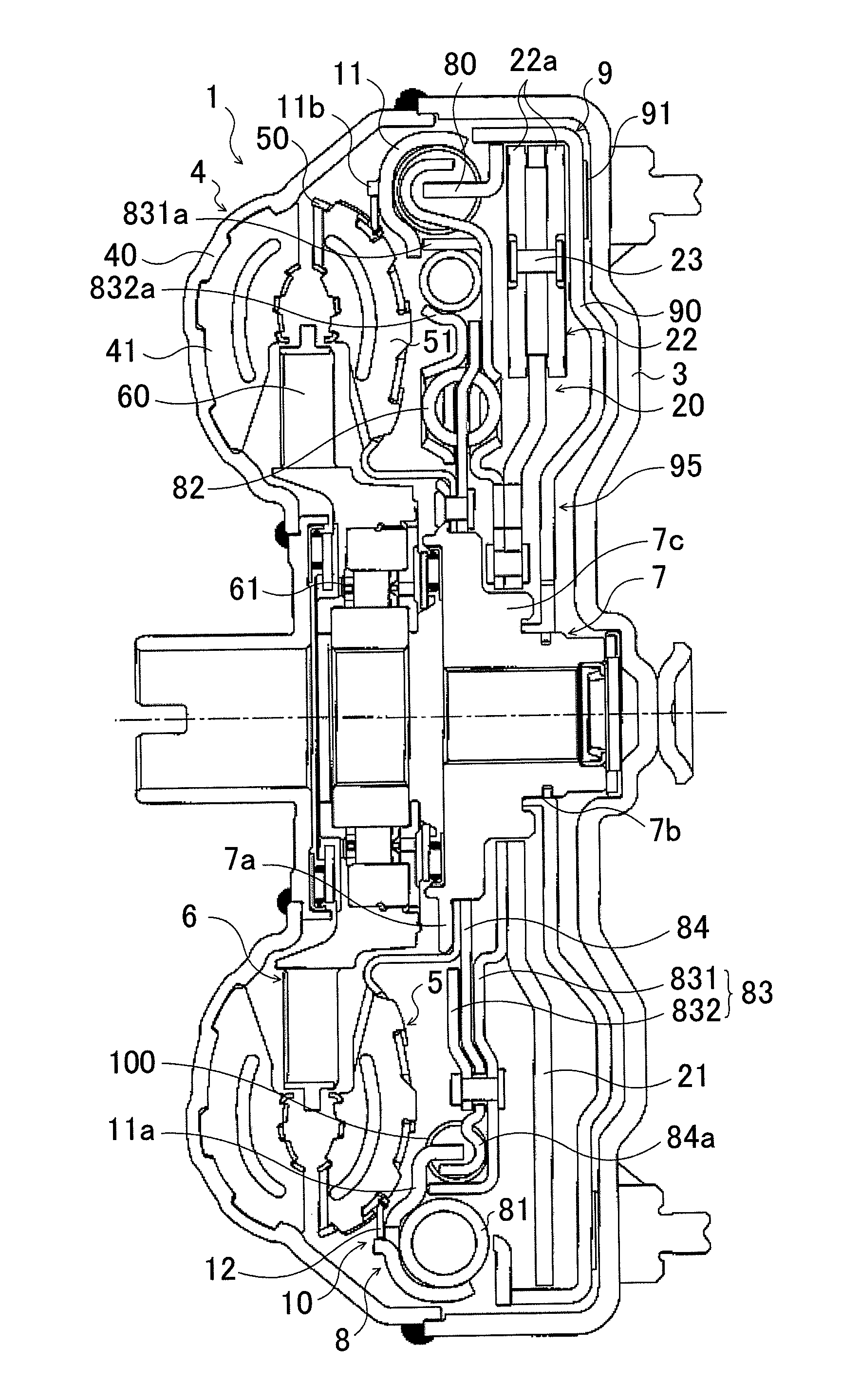
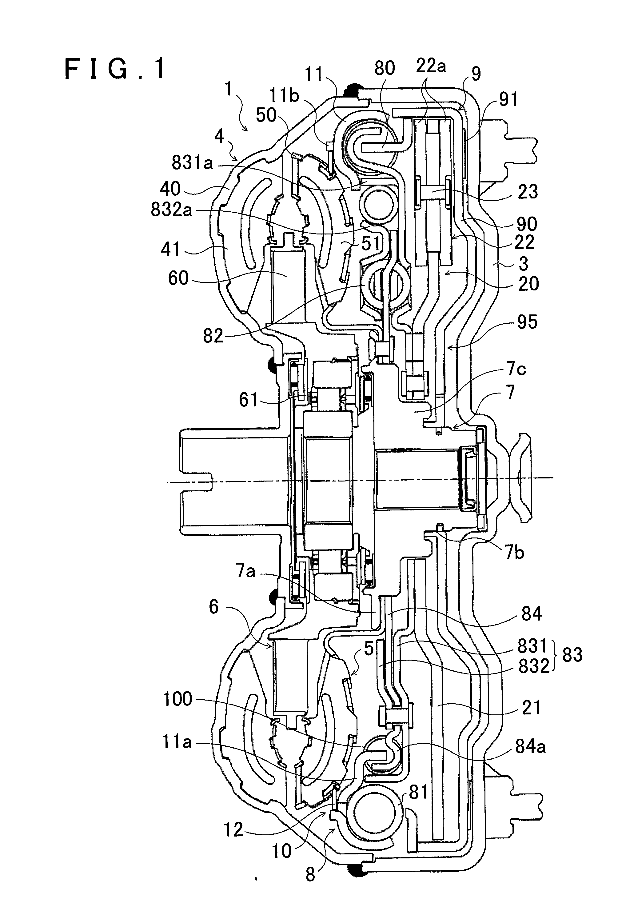
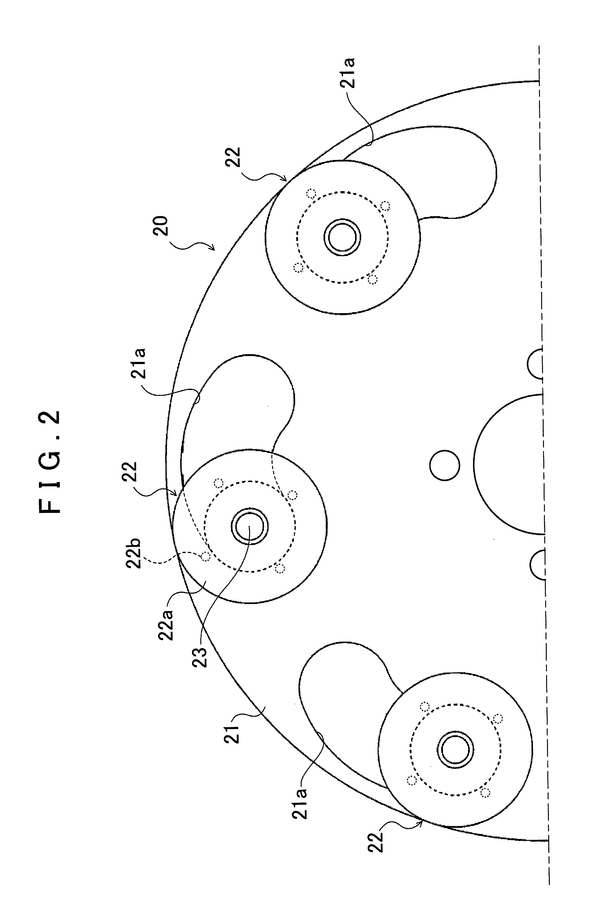
[0030]FIG. 1 is a structure diagram that shows a fluid transmission apparatus 1, which serves as a starting apparatus, according to one embodiment of the invention. The fluid transmission apparatus 1 shown in the drawing is a torque converter that is mounted as the starting apparatus on a vehicle equipped with an engine (internal combustion engine) that serves as a motor. The fluid transmission apparatus 1 includes a front cover (input member) 3 that is coupled to a crankshaft of the engine (not shown), a pump impeller (input-side fluid transmitting element) 4 that is fixed to the front cover 3, a turbine runner (output-side fluid transmitting element) 5 that is rotatable coaxially with the pump impeller 4, a stator 6 that rectifies the flow of hydraulic oil (hydraulic fluid) from the turbine runner 5 to the pump impeller 4, a damper hub (output member) 7 that is fixed to an i...


PUM


Abstract

A starting apparatus including an input member coupled to a motor; a damper mechanism having an input element, an elastic body and an output element; a lock-up clutch mechanism for performing lockup where the input member is coupled to an input shaft of a transmission via the damper mechanism and for canceling lockup, and a dynamic damper including an elastic body and a mass body engaged with the elastic body. The mass body of the dynamic damper is an elastic body support member that is supported rotatably around an axis of the starting apparatus and that supports the elastic body of the damper mechanism. With this arrangement, the dynamic damper is easily adjustable while reducing the overall size of the starting apparatus.

Description

INCORPORATION BY REFERENCE[0001]The disclosure of Japanese Patent Application No. 2010-222771 filed on Sep. 30, 2010 including the specification, drawings and abstract is incorporated herein by reference in its entirety.BACKGROUND OF THE INVENTION[0002]The present invention relates to a starting apparatus that includes a dynamic damper.DESCRIPTION OF THE RELATED ART[0003]There has been suggested, as a conventional starting apparatus of this type, a fluid transmission apparatus which includes: a pump impeller that is connected to an input member coupled to a motor; a turbine runner that is rotatable together with the pump impeller; a damper mechanism that has an input element, an intermediate element engaged with the input element via first elastic bodies and an output element engaged with the intermediate element via second elastic bodies and coupled to an input shaft of a transmission; a lock-up clutch mechanism that is able to carry out lockup where the input member is engaged wit...

Claims


Application Information

Patent Timeline
IPC IPC(8): F16H45/02
CPCF16H45/02F16H2045/0205F16H2045/0226F16F15/145F16H2045/0263F16H2045/0294F16F15/12366F16H2045/0231
Inventor TAKIKAWA, YOSHIHIROMARUYAMA, KAZUTOITOU, KAZUHIRO
Owner AISIN AW CO LTD
Why Eureka
Try Eureka