Vehicle Drive Device

a technology of drive device and rotor, which is applied in the direction of engine-driven generators, mechanical actuated clutches, transportation and packaging, etc., can solve the problems of increasing the weight of the oil pump itself, increasing the cost of the engine, and reducing the energy efficiency. , to achieve the effect of accurate detection of the rotational position of the rotor and increasing the cos

Inactive Publication Date: 2012-04-05
AISIN AW CO LTD
View PDF0 Cites 40 Cited by
  • Summary
  • Abstract
  • Description
  • Claims
  • Application Information

AI Technical Summary

Benefits of technology

[0026]According to the seventh aspect, the oil collection portion can be formed between the sensor rotor of the rotation sensor and the rotor support member utilizing the sensor rotor. In many cases, the vehicle drive device including the rotary electric machine serving as a drive force source for the vehicle is prov

Problems solved by technology

In such a configuration, in order to secure sufficient capability to cool the friction members, it is necessary to supply a large amount of oil to the friction members, which requires

Method used


Image

  • Vehicle Drive Device
  • Vehicle Drive Device
  • Vehicle Drive Device

Examples


first embodiment

1. First Embodiment

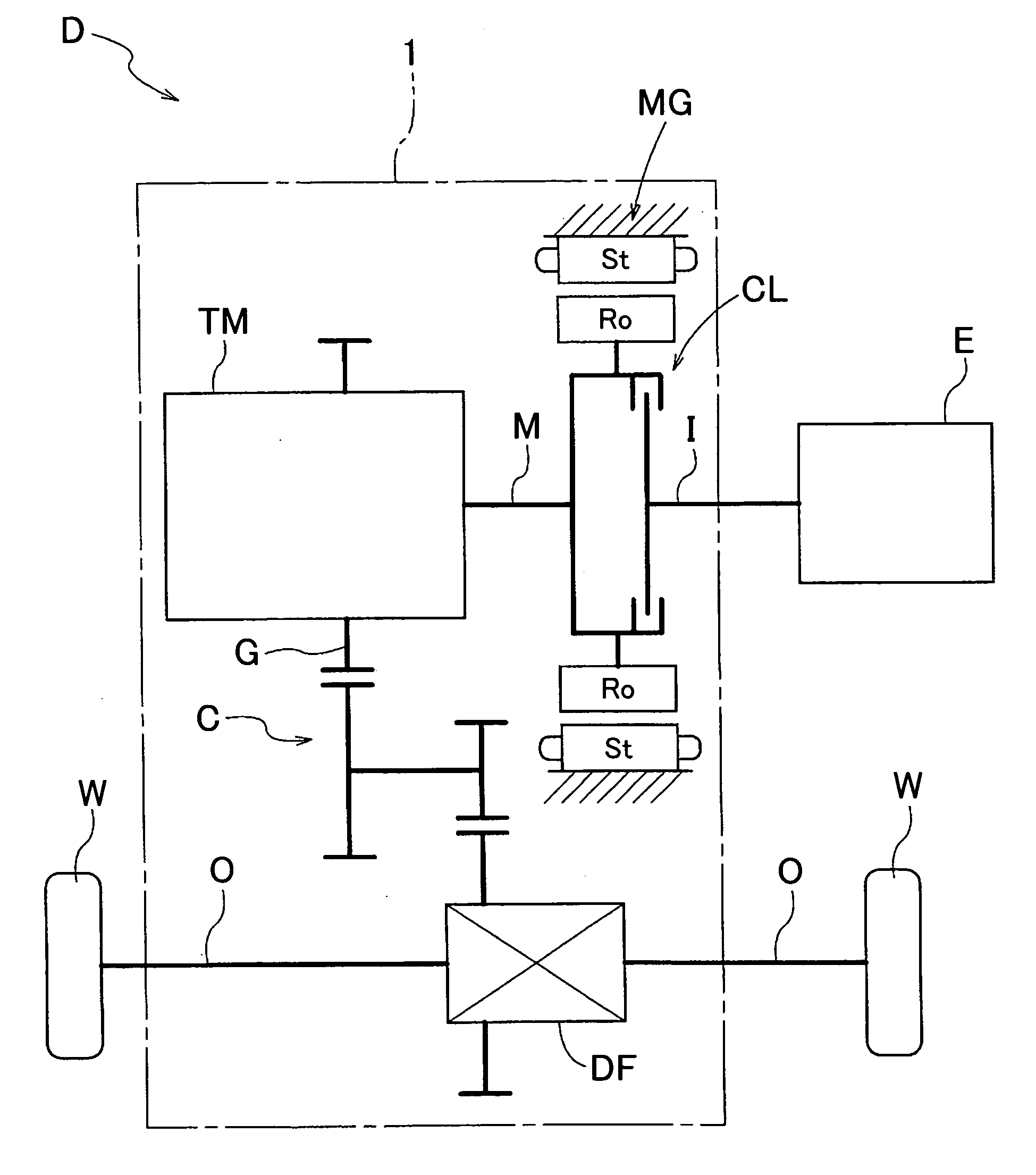
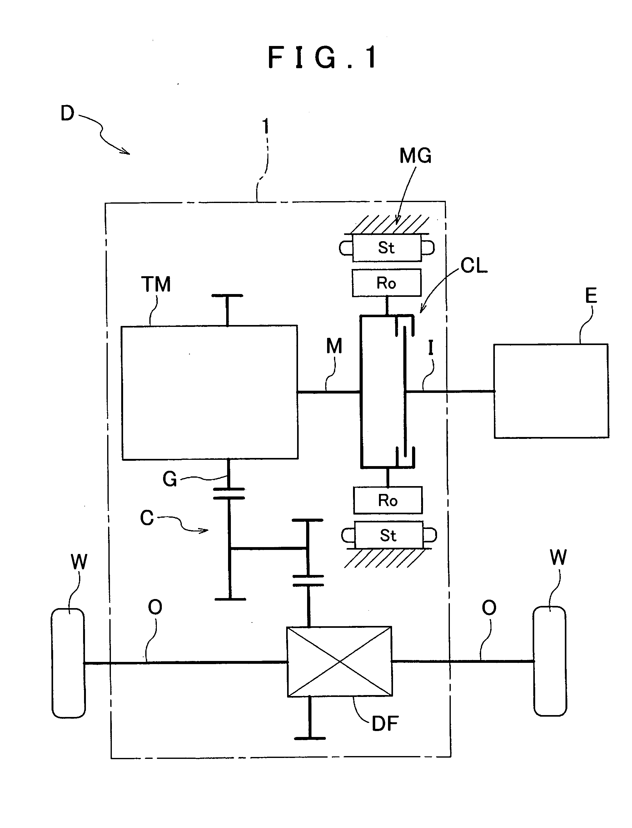
[0033]A first embodiment of the present invention will be described with reference to the drawings. FIG. 1 is a schematic diagram showing a schematic configuration of a drive device D according to the embodiment. The drive device D is a drive device (hybrid drive device) for a hybrid vehicle that uses one or both of an internal combustion engine E and a rotary electric machine MG as a drive force source for wheels W of the vehicle. The drive device D is formed as a drive device for a so-called one-motor parallel type hybrid vehicle. The drive device D according to the embodiment will be described in detail below.

[0034]1-1. Overall Configuration of Drive Device

[0035]As shown in FIG. 1, the drive device D includes an input shaft I drivably coupled to the internal combustion engine E, output shafts O drivably coupled to the wheels W, the rotary electric machine MG a speed change mechanism TM, and an intermediate shaft M drivably coupled the rotary electric machine MG...

second embodiment

2. Second Embodiment

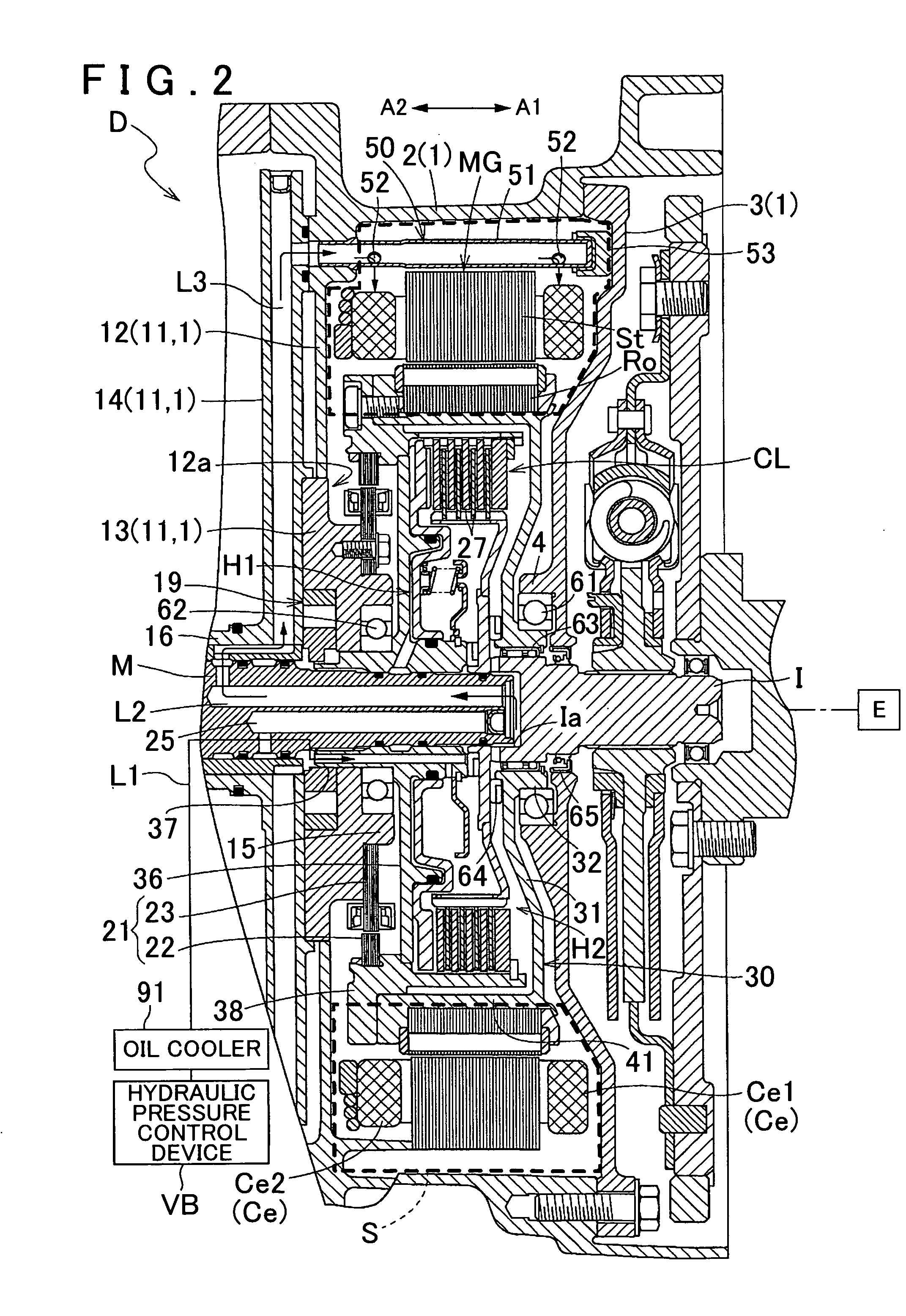
[0083]A second embodiment of the present invention will be described with reference to FIG. 6. Also in the embodiment, a vehicle drive device according to the present invention is applied to a drive device D for a hybrid vehicle. The overall configuration of the drive device D according to the embodiment and the configuration of respective components of the drive device D are basically the same as those in the first embodiment described above. It should be noted, however, that the embodiment is different from the first embodiment described above in that the third oil passage L3, which is a main constituent element of the cooling structure for the rotary electric machine MG, is formed below (vertically below) the intermediate shaft M. The differences from the first embodiment will be described below. The same elements as those in the first embodiment described above will not be specifically described.

[0084]In the embodiment, the radial oil passage L2c (see FIG. 3)...


PUM


Abstract

A vehicle drive device configured with an input member drivably coupled to an internal combustion engine, an output member drivably coupled to wheels, and a friction engagement device that selectively drivably couples the input member and the output member to each other. A rotary electric machine is connected between the input member and the output member. A housing oil chamber houses at least friction members of the friction engagement device and is filled with oil. A housing space houses the rotary electric machine, a first oil passage through which oil is supplied to the housing oil chamber, a second oil passage through which oil is discharged from the housing oil chamber; and a third oil passage through which oil discharged from the second oil passage is supplied to the housing space.

Description

[0001]The disclosure of Japanese Patent Applications No. 2011-043269 filed on Feb. 28, 2011 and No. 2010-213447 filed on Sep. 24, 2010 including the specification, drawings and abstract is incorporated herein by reference in its entirety.BACKGROUND OF THE INVENTION[0002]The present invention relates to a vehicle drive device including an input member drivably coupled to an internal combustion engine, an output member drivably coupled to wheels, a friction engagement device that selectively drivably couples the input member and the output member to each other, and a rotary electric machine provided on a power transfer path connecting between the input member and the output member.DESCRIPTION OF THE RELATED ART [0003]A device disclosed in Japanese Patent Application Publication No. JP-A-2009-72052 mentioned below is already known as an example of the vehicle drive device described above. Hereinafter, in the description in the “Description of the Related Art” section, reference numeral...

Claims


Application Information

Patent Timeline
IPC IPC(8): F16D13/72B60L50/16
CPCB60K6/40B60K6/48B60K2006/4825B60L11/14H02K7/006Y02T10/70Y02T10/7077Y02T10/641Y02T10/6221Y02T10/6252H02K9/19B60L50/15B60L50/16Y02T10/62Y02T10/64Y02T10/7072F16D25/123F16D25/0638
Inventor KASUYA, SATORUKITOU, MASASHISEKI, YUICHITAKAHASHI, YUSUKESUGISAKA, SHIGERU
Owner AISIN AW CO LTD
Why Eureka
Try Eureka