
Control device of a driving apparatus

Inactive Publication Date: 2012-04-05
AISIN AW CO LTD
View PDF0 Cites 6 Cited by
  • Summary
  • Abstract
  • Description
  • Claims
  • Application Information

AI Technical Summary

Benefits of technology

[0007]Thus, the present invention provides technology capable of keeping induced voltage within a voltage resistance limit of an inverter, without increasing the size of a control device that controls a driving apparatus that includes a variable magnetic flux-type rotary electric machine.
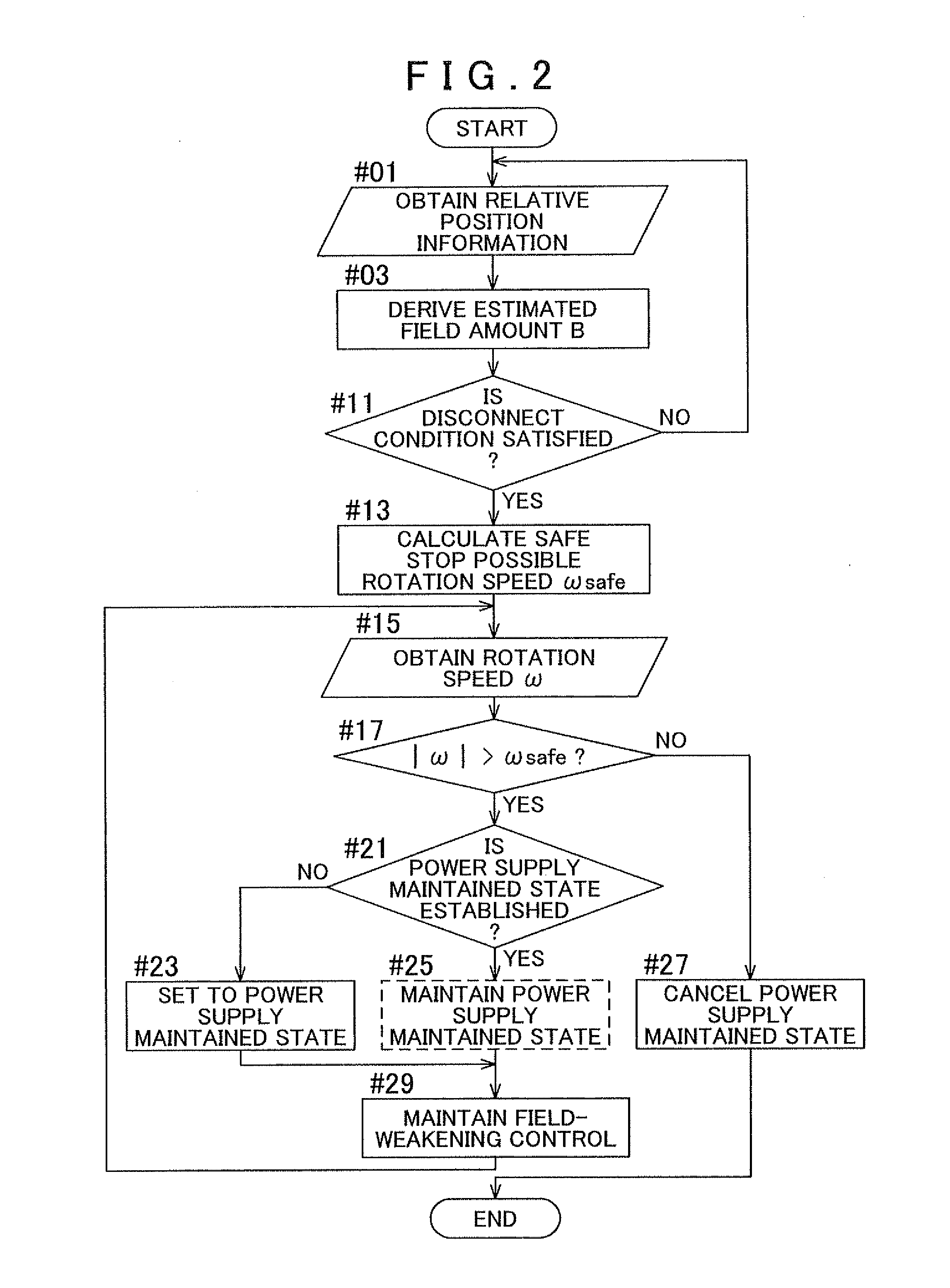
[0009]According to the first aspect, if it is determined that the overvoltage state exists when the disconnect condition is satisfied, connection with the main power supply is maintained regardless of the disconnect condition, at least until the overvoltage state is eliminated. The connection with the main power supply is maintained, so the control device is able to control the rotary electric machine by field-weakening control that supplies a weakened field current that weakens the field flux to the coil. Therefore, even if an unexpected event occurs, e.g., if a condition that the connection with the main power supply be disconnected is satisfied, during high speed operation with a strong field flux, it is possible to inhibit high induced voltage from being generated by the rotor that continues to rotate from inertia. When the inertia force weakens and the rotation speed of the rotor decreases, the induced voltage also decreases. After the overvoltage state has been eliminated, the main power supply is disconnected according to the disconnect condition, so the main power supply can also be appropriately controlled. In this way, according to the first aspect, it is possible to keep the induced voltage within the voltage resistance limit of the inverter, without increasing the size of a control device of a driving apparatus that controls a driving apparatus provided with a variable magnetic field-type rotary electric machine.
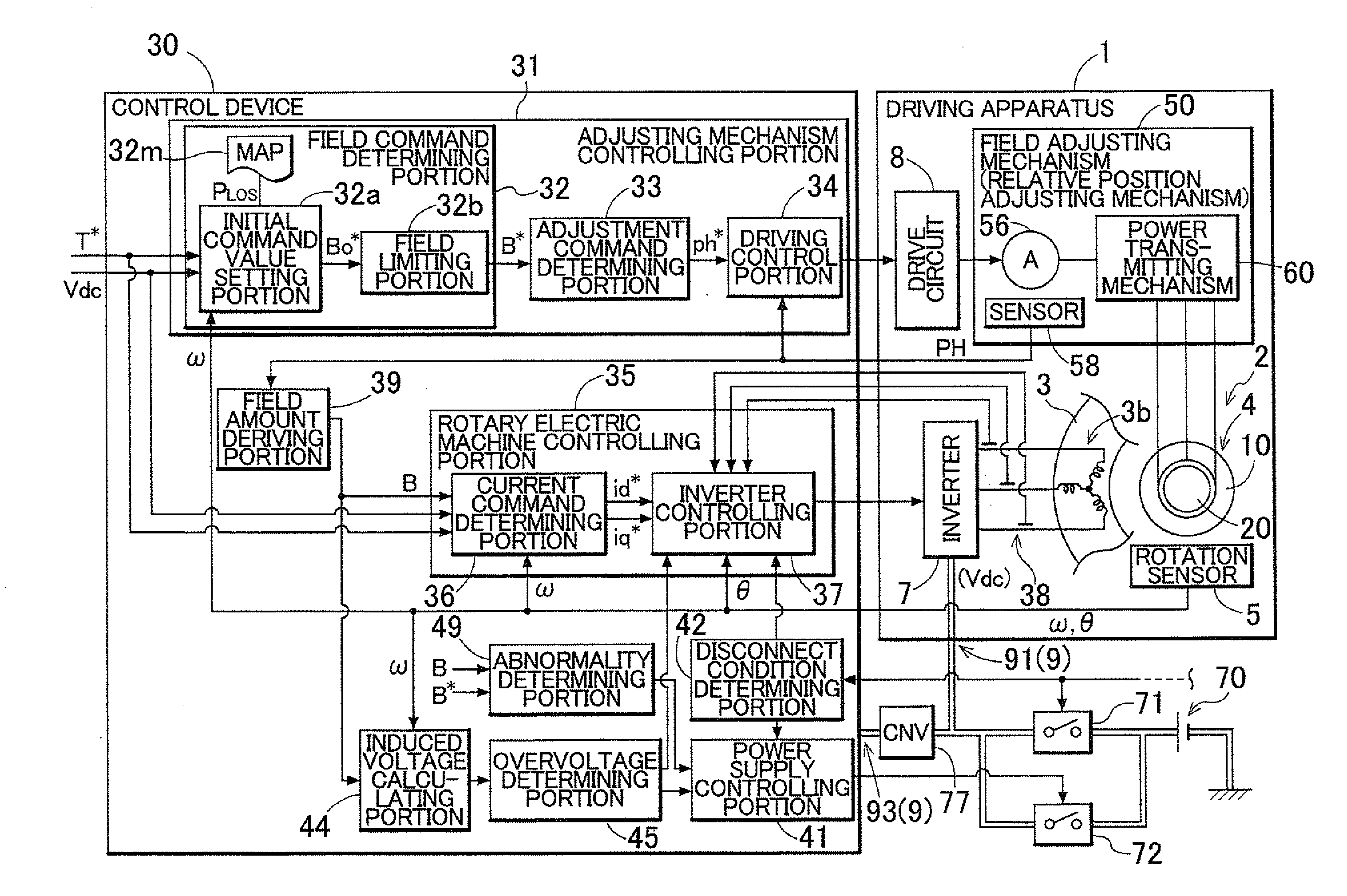
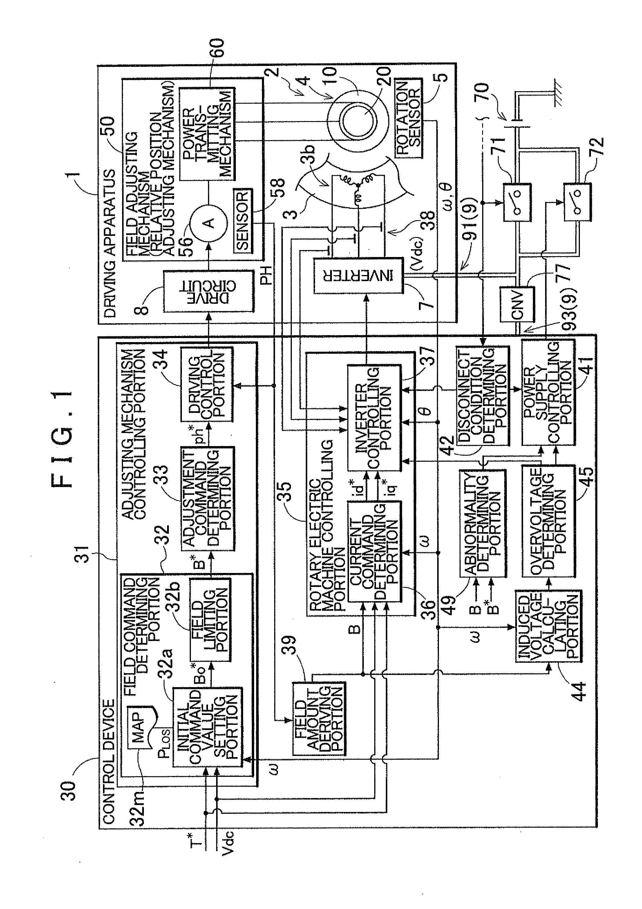
[0012]According to a third aspect of the present invention, the rotary electric machine controlling portion of the control device of a driving apparatus according to the present invention may determine a current command that is a target value for a driving current supplied to the coil, based on at least the estimated field amount, a target torque of the rotary electric machine, and the rotation speed, and control the rotary electric machine. When the field flux is constant, the current command is typically determined based on the target torque and the rotation speed. However, the current command for outputting the target torque differs depending on the strength of the field flux, so it is preferably determined taking the strength of the field flux into account. According to the third aspect, the current command is determined based on the estimated field amount, the target torque, and the rotation speed. Therefore, a driving apparatus in which the field flux is not constant can be controlled better following the changing field flux.
[0013]Also, according to a fourth aspect of the present invention, the field adjusting mechanism of the control device of a driving apparatus according to the present invention may be a mechanism that adjusts the field flux by displacing at least a portion of the rotor in a circumferential direction or a direction of a rotational axis of the rotor, and may include a driving source that supplies driving force for the displacement, and a power transmitting mechanism that transmits the driving force from the driving source to the rotor. According to the fourth aspect, the field flux is adjusted by displacing at least a portion of the rotor, so the field flux can be adjusted without intermittently flowing weakened field current that reduces efficiency and the like.
[0014]Here, according to a fifth aspect of the present invention, the rotor may include a first rotor and a second rotor that each have a rotor core and of which a relative position is adjustable, and the permanent magnet may be provided in the rotor core of at least one of the rotors. Also, the field adjusting mechanism may be a relative position adjusting mechanism that adjusts the field flux by displacing the relative position in a circumferential direction. The circumferential direction of the rotor is the direction corresponding to an electrical angle, so the relative position (the relative phase) of the electrical angle of the two rotors can be changed by displacing the relative position of the two rotors in the circumferential direction. As a result, the magnetic circuit through which the magnetic flux of the permanent magnet passes changes, so the field flux supplied to the stator can be better adjusted.

Problems solved by technology

However, if the disconnect condition is suddenly satisfied and the main power supply is disconnected, the field-weakening control or the like will not be able to be performed, so induced voltage that exceeds the voltage resistance of the inverter may be generated by the rotor that continues to rotate due to inertia.

Method used


Image

  • Control device of a driving apparatus
  • Control device of a driving apparatus
  • Control device of a driving apparatus

Examples


Embodiment Construction

[0028]Hereinafter, an example in which a preferred example embodiment of the present invention is applied to a control device of a driving apparatus that is mounted in a vehicle, for example, and provides driving force to that vehicle will be described with reference to the drawings. FIG. 1 is a view showing a frame format of the overall structure of a driving apparatus 1 and a control device 30 of the driving apparatus according to the present invention. As shown in FIG. 1, the driving apparatus 1 includes a rotary electric machine 2 and a field adjusting mechanism 50, an inverter 7 that drives the rotary electric machine 2, and a drive circuit 8 that drives the field adjusting mechanism 50. The rotary electric machine 2 includes a rotor 4 that has permanent magnets, and a stator 3 that has a coil (i.e., a stator coil) 3b. The rotor 4 is configured to change a field flux that links to the coil 3b that generates a rotating magnetic field according to the relative positions, in the c...


PUM


Abstract

A control device for a driving apparatus. The control device is configured with a device that controls the rotary electric machine via the inverter, a device that determines whether a disconnect condition of the main power supply is satisfied, and a device that obtains an estimated field amount that is an estimated value of the field flux supplied from the rotor to the stator. The control device is also configured with a device calculates an induced voltage that is induced in the coil, and a device that determines whether an overvoltage state in which the induced voltage exceeds a voltage resistance of the inverter exists. If it is determined that an overvoltage state exists when the disconnect condition is satisfied, connection with a main power supply is maintained until the overvoltage state is eliminated. The rotary electric machine is controlled by weakening the field flux to the coil.

Description

INCORPORATION BY REFERENCE[0001]The disclosure of Japanese Patent Application No. 2010-222964 filed on Sep. 30, 2010 including the specification, drawings and abstract is incorporated herein by reference in its entirety.BACKGROUND OF THE INVENTION[0002]The present invention relates to a control device of a driving apparatus that includes a variable magnetic flux-type rotary electric machine in which a field flux provided by a rotor having a permanent magnet can be adjusted, and a mechanism that adjusts this field flux.DESCRIPTION OF THE RELATED ART[0003]Interior permanent magnet synchronous motors (IPMSM) that have a rotor with permanent magnets embedded inside of them are widely used. With an IPMSM, the permanent magnets are typically fixed to a rotor core, so the magnetic flux generated by the rotor is constant. The induced voltage generated in the stator coil becomes higher as the rotation speed of the rotor increases, and if the induced voltage exceeds the driving voltage, contr...

Claims


Application Information

Patent Timeline
IPC IPC(8): H02P6/06H02K21/14H02P21/00H02P21/06H02P21/12H02P27/04
CPCH02P6/06H02K21/029
Inventor HISADA, HIDEKIISHIKAWA, MASAMI
Owner AISIN AW CO LTD
Learn More