Burglarproof security system and installing method thereof

a security system and burglarproof technology, applied in the field of burglarproof security system, can solve the problems of breakage, man-made damage or other criminal events, and reducing the possibility of burglary, and achieve the effect of prompting warning information

Inactive Publication Date: 2012-04-05
YUN XIANG TECH
View PDF8 Cites 9 Cited by
  • Summary
  • Abstract
  • Description
  • Claims
  • Application Information

AI Technical Summary

Benefits of technology

[0006]The present invention provides a burglarproof security system applied to a substrate (e.g. a glass plate, an acrylic plate or a ceramic plate) in order to accurately prompt the warning information and meet the cost-effective requirement.

Problems solved by technology

Generally, when burglars believe no one is around a home or a car and the home or the car appears to be easy to get inside, they may break into the home or the car to take valuable possessions.
The use of the burglarproof security system may reduce the possibility of incurring burglary, breakage, man-made damage or other criminal events.
The conventional burglarproof security system, however, still has some drawbacks.
A strong wind, an earthquake, a passage of a large-sized vehicle, erroneous touch of a person or a push of the glass plate 10 may result in vibration.
The guard or the security service personnel is usually perplexed at the high false-alarm rate.
In this situation, the burglarproof security efficacy is largely impaired.

Method used


Image

  • Burglarproof security system and installing method thereof
  • Burglarproof security system and installing method thereof
  • Burglarproof security system and installing method thereof

Examples


Embodiment Construction

[0026]The present invention will now be described more specifically with reference to the following embodiments. It is to be noted that the following descriptions of preferred embodiments of this invention are presented herein for purpose of illustration and description only. It is not intended to be exhaustive or to be limited to the precise form disclosed.

[0027]The present invention provides a burglarproof security system applied to a substrate. The present invention is illustrated by referring a glass plate, an acrylic plate or a ceramic plate as a substrate. Nevertheless, the substrate is not restricted to the glass plate, the acrylic plate and the ceramic plate.

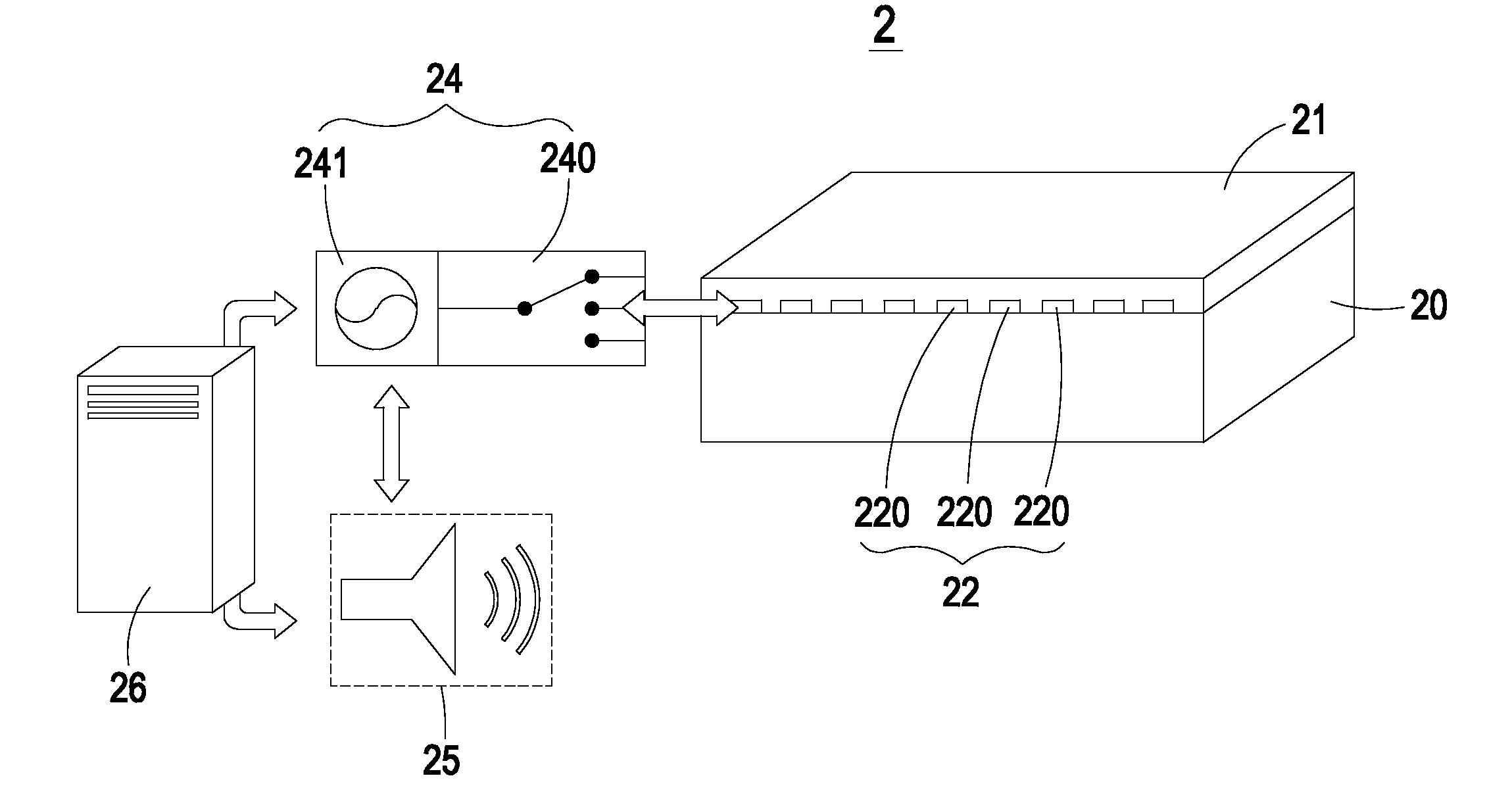
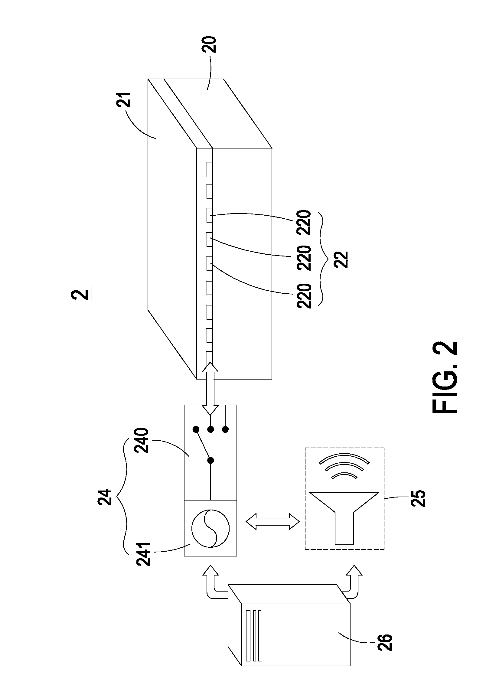
[0028]FIG. 2 is a schematic diagram illustrating a burglarproof security system applied to a substrate according to an embodiment of the present invention. FIG. 3 is a schematic diagram illustrating a burglarproof security system applied to a substrate according to another embodiment of the present invention. The burglar...


PUM

PropertyMeasurementUnit
electric poweraaaaaaaaaa
capacitanceaaaaaaaaaa
translucentaaaaaaaaaa

Abstract

A burglarproof security system includes a substrate, a conducting wire layer, a sensing control unit, an alarm device and a power supply. The conducting wire layer is disposed on the substrate, and includes plural conducting wires. The plural conducting wires collectively define either a resistive sensing circuit or a capacitive sensing circuit. The sensing control unit is electrically connected with the plural conducting wires of the conducting wire layer for controlling and selectively switching the plural conducting wires to define either the resistive sensing circuit or the capacitive sensing circuit, and detecting the resistive sensing circuit or the capacitive sensing circuit, thereby generating a detecting signal. When the detecting signal from the sensing control unit is received by the alarm device, the alarm device generates a warning signal. The power supply is electrically connected with the sensing control unit and the alarm device for providing electric power.

Description

FIELD OF THE INVENTION[0001]The present invention relates to a burglarproof security system, and more particularly to a burglarproof security system applied to a substrate (e.g. a glass plate, an acrylic plate or a ceramic plate). The present invention also relates to a method of installing the burglarproof security system.BACKGROUND OF THE INVENTION[0002]Generally, when burglars believe no one is around a home or a car and the home or the car appears to be easy to get inside, they may break into the home or the car to take valuable possessions. One of the best ways to deter burglars from going into the home or the car is to install a burglarproof security system. The use of the burglarproof security system may reduce the possibility of incurring burglary, breakage, man-made damage or other criminal events. As known, one of the common burglarproof security systems utilizes a vibration sensor to judge whether a glass plate is broken by a foreign article.[0003]FIG. 1 is a schematic di...

Claims


Application Information

Patent Timeline
Patent Type & Authority Applications(United States)
IPC IPC(8): G08B13/00H01R43/00
CPCG08B13/04Y10T29/49117G08B13/26
Inventor HU, CHIN-WANG
Owner YUN XIANG TECH
Why Eureka
Try Eureka