Display panel driving device

a technology for driving devices and display panels, applied in the direction of instruments, computing, electric digital data processing, etc., can solve the problems of increasing power consumption and manufacturing costs, and achieve the effect of increasing power consumption and manufacturing costs, and maintaining the duty ratio of clock signals

Active Publication Date: 2012-04-05
LAPIS SEMICON CO LTD
View PDF5 Cites 13 Cited by
  • Summary
  • Abstract
  • Description
  • Claims
  • Application Information

AI Technical Summary

Benefits of technology

[0010]An object of the present invention is to provide a display panel driving device which supplies a clock signal through a plurality of driver chips connecte

Problems solved by technology

However, the PLL and DLL circuits are large in size, resulting in

Method used


Image

  • Display panel driving device
  • Display panel driving device
  • Display panel driving device

Examples


Embodiment Construction

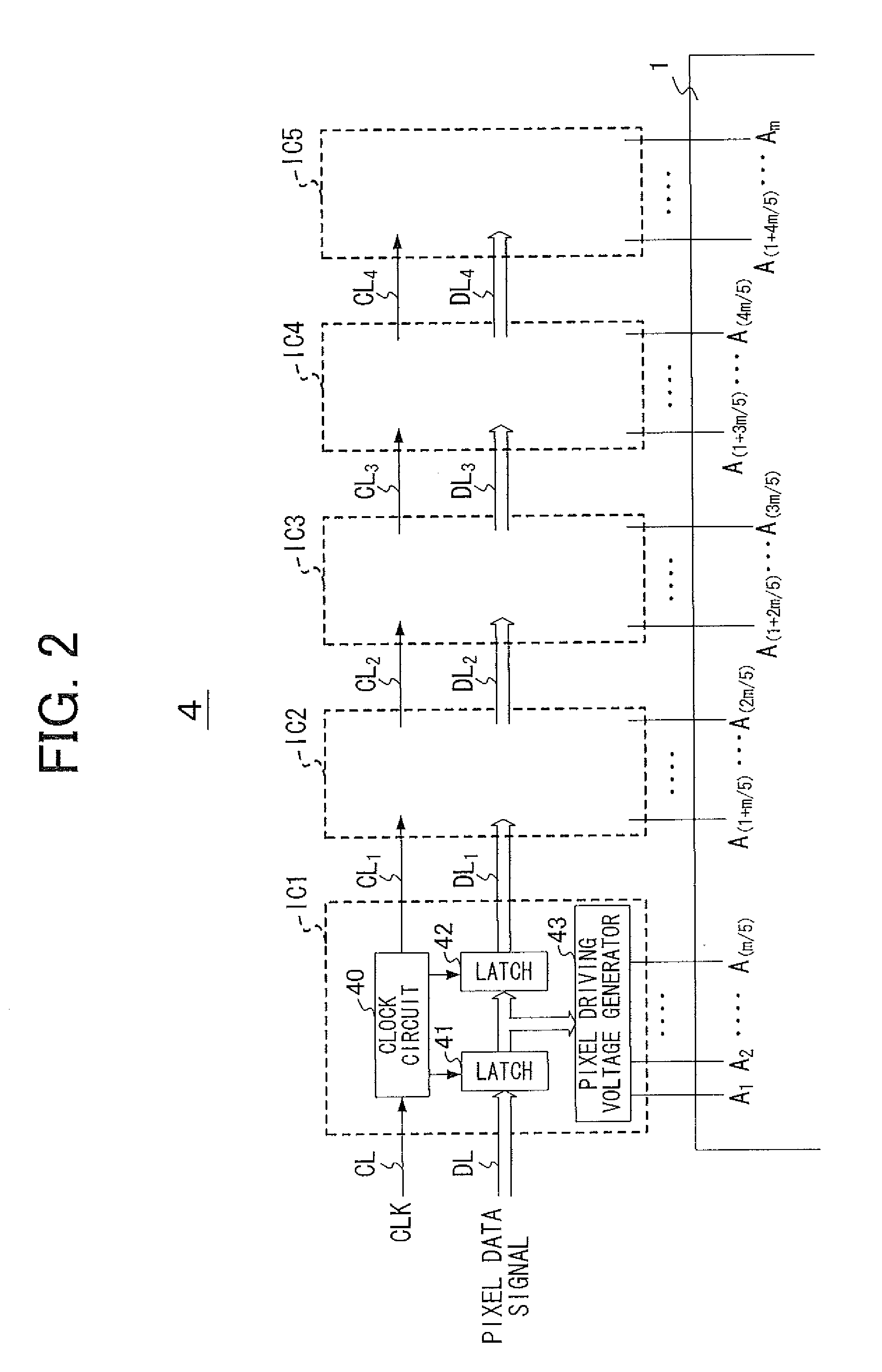
[0028]In a display panel driving device of the present invention, a signal line driver, which applies a pixel driving voltage based on an input image signal to each signal line of a display panel at a timing corresponding to a clock signal, is built by a plurality of driver chips that are connected in cascade by the clock line. The clock transmission unit is provided in each driver chip in the following manner: The clock transmission unit transmits to a subsequent driver chip a shaped clock signal having a first level when a logic level of a ½ frequency clock signal is equal to a logic level of a delayed ½ frequency clock signal, or a shaped clock signal having a second level when the logic levels of the two clock signals are different.

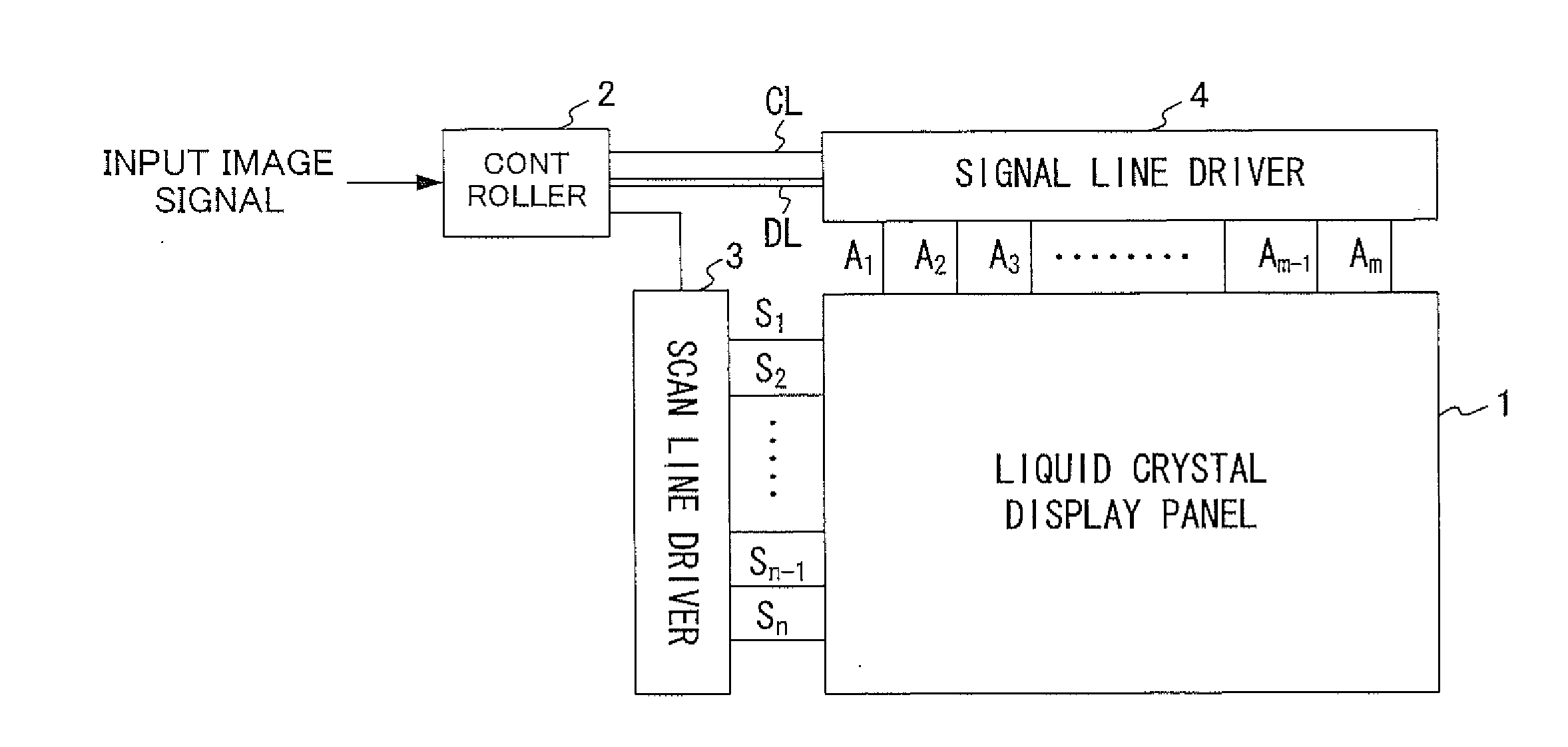
[0029]Referring to FIG. 1, a schematic configuration of a liquid crystal display device having a liquid crystal display panel 1 is described.

[0030]In FIG. 1, the liquid crystal display panel 1 includes a plurality of scan lines S1 to Sn (n is an integ...


PUM


Abstract

A display panel driving device has a signal line driver. The signal line driver applies a pixel driving voltage based on an input image signal to each signal line of a display panel at a timing corresponding to a clock signal. The signal line driver is divided into a plurality of driver chips connected in cascade by the clock line. The display panel driving device supplies a clock signal through the driver chips. The duty ratio of the clock signal is stabilized when the clock signal passes through the driver chips, without leading to an increase in power consumption and in manufacturing costs.

Description

BACKGROUND OF THE INVENTION[0001]1. Field of the Invention[0002]The present invention relates to a display panel driving device that drives a display panel.[0003]2. Description of Related Art[0004]A liquid crystal display device includes a liquid crystal display panel. The liquid crystal display panel has a plurality of scan lines and a plurality of signal lines. The signal lines cross each of the scan lines. The liquid crystal display panel also has pixel units, which are formed at portions where the scan lines and signal lines cross each other. The liquid crystal display device also includes a display panel driving device. The driving device has a scan line driver, which supplies a selection signal to each of the scan lines, and a signal line driver, which supplies a pixel data signal to each of the signal lines.[0005]The signal line driver is divided into a plurality of driver ICs (Integrated Circuits) (see FIG. 2 of Japanese Patent Application (Kokai) Publication No. 10-153760, ...

Claims


Application Information

Patent Timeline
IPC IPC(8): G06F3/038
CPCG09G3/20G09G3/3685G09G2330/021G09G2310/08G09G2320/041G09G2310/027
Inventor TOMITA, TAKASHI
Owner LAPIS SEMICON CO LTD
Why Eureka
Try Eureka