Timestamp predictor for packets over a synchronous protocol

a synchronous protocol and packet technology, applied in the field of synchronization of clocks in a communication network, can solve the problems of cumulative detriment, errors or inaccuracy in handling timing-related messages, and detrimental to accurate clock synchronization

Active Publication Date: 2012-04-05
MICROSEMI STORAGE SOLUTIONS
View PDF3 Cites 36 Cited by
  • Summary
  • Abstract
  • Description
  • Claims
  • Application Information

AI Technical Summary

Benefits of technology

[0012]These and other aspects of the invention are m

Problems solved by technology

Any errors or inaccuracies in handling the timing-related messages may be detrimental to accu

Method used


Image

  • Timestamp predictor for packets over a synchronous protocol
  • Timestamp predictor for packets over a synchronous protocol
  • Timestamp predictor for packets over a synchronous protocol

Examples


Embodiment Construction

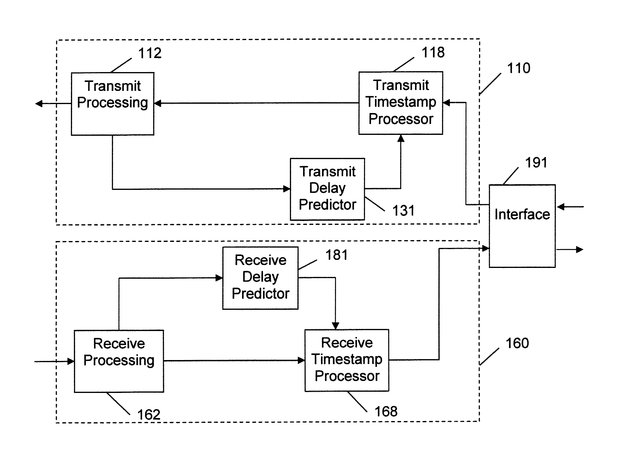
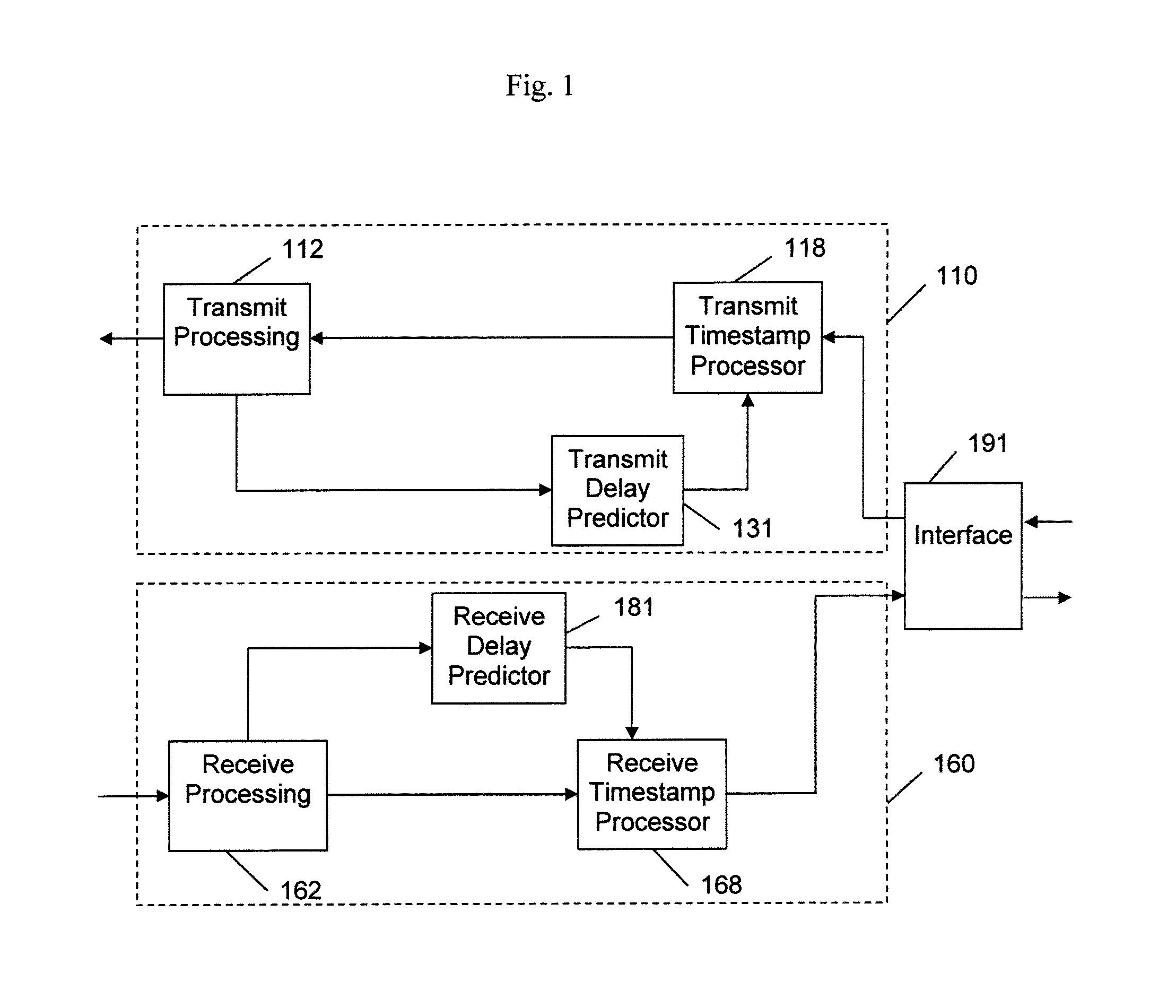
[0019]FIG. 1 is a block diagram of a physical layer communication device (PHY) in accordance with aspects of the invention. The PHY includes a receive path block 160 to receive an input signal from a communication network and a transmit path block 110 to transmit an output signal to the communication network. The PHY also includes an interface block 191 for coupling to higher-level devices. In some embodiments, various other processing or formatting blocks may also be included in the signal path between the receive path block 160 and the interface block 191 and the transmit path block 110 and the interface block 191. The blocks of the PHY are generally implemented with electronic circuitry. For example, in one embodiment the PHY is provided in a CMOS integrated circuit. Software programming may be used to control operation of some circuitry in the PHY. In one embodiment, a programmable processor is used to configure the circuitry of the PHY and to handle exception conditions.

[0020]T...


PUM


Abstract

A physical layer communication device (PHY) transmits and receives signal to and from a communication link using a synchronous protocol. The PHY communicates with a higher-layer device using a packet protocol. Timestamp values contained in timing-related messages in some packets are written or modified by the PHY. Delays incurred in transmitting and receiving the packets are predicted and used in setting the timestamp values.

Description

BACKGROUND OF THE INVENTION[0001]The present invention relates generally to synchronization of clocks and, more particularly, to synchronization of clocks in a communication network including packets communicated using a synchronous protocol.[0002]It may be advantageous for devices in a networked system to have a common time base. The common time base may be used, for example, to trigger coordinated measurement instances in a network of sensors or to coordinate actions of controllers in an industrial system. In addition to sensors and controllers, the system may include computers and communication devices, such as routers.[0003]The electronics industry has developed several standard protocols for use in synchronizing clocks, for example, the Precision Time Protocol (PTP) of IEEE 1588. PTP includes sending timing-related messages between nodes in a communication network. The timing-related messages include, for example, a node transmitting a time-stamped packet to supply its time bas...

Claims


Application Information

Patent Timeline
IPC IPC(8): H04L12/56
CPCH04J3/0682H04J3/0685H04L41/147H04J3/0697H04L43/106H04J3/0691H04J2203/0082H04L43/0852H04L41/149H04L7/0091
Inventor SWARTZENTRUBER, RONRAO, GANESH
Owner MICROSEMI STORAGE SOLUTIONS
Why Eureka
Try Eureka